You are using an out of date browser. It may not display this or other websites correctly.
You should upgrade or use an alternative browser.
You should upgrade or use an alternative browser.
Lishen 272AH thread?
- Thread starter nebulight
- Start date
Nice. Now the fun starts getting them charged.I have now completed my first Lishen 272Ah test as well. 285,64Ah removed. Two cells at 2,891v and one cell at 2,754v and one at 2,810v
Yes, they are charging now at 50 amps.. Hopefully they will stay balanced..
Top balance at 50 amps? How are you doing that? Or did you already top balance.
stobbie
New Member
- Joined
- Aug 25, 2020
- Messages
- 49
I did allready topbalance them, but did that at 50 amps 3,65v as well!
I've bought this great converted server power supply on ali... : https://www.aliexpress.com/item/4000280014850.html
I've bought this great converted server power supply on ali... : https://www.aliexpress.com/item/4000280014850.html
I wish I had bought that power supply. I'm on day three of my top balance and I'm still under 3.4 volts.I did allready topbalance them, but did that at 50 amps 3,65v as well!
I've bought this great converted server power supply on ali... : https://www.aliexpress.com/item/4000280014850.html
Just ordered 16 x 272s off an alibaba, first time lifeper here, gotta research all the tools and balancing, any recommendations? Will be making my own bus bars as these will not come with them for a discounted price. Making a 16s 48v setup with overkill BMS. If they come balanced, can i just slap the BMS on it and start using?
FilterGuy
Solar Engineering Consultant - EG4 and Consumers
Will recommends a good set of tools on his site. https://www.mobile-solarpower.com/tools.htmlJust ordered 16 x 272s off an alibaba, first time lifeper here, gotta research all the tools and balancing, any recommendations?
I put up a couple of papers about balancing.
https://diysolarforum.com/resources/explanation-for-beginners-of-top-and-bottom-balance.118/
and
https://diysolarforum.com/resources/explanation-for-beginners-of-top-and-bottom-balance.118/
onlinemetals.com is the best place I have found for copper bar. https://www.onlinemetals.com/en/buy/copper-rectangle-barWill be making my own bus bars as these will not come with them for a discounted price.
If you know of a better source, please let us know.
If they come balanced, can i just slap the BMS on it and start using?
You have no good way of knowing if they are balanced when you get them. (The same voltage does not mean they are balanced)
After you balance them and set up the battery, you will probably need to adjust your voltages.
https://diysolarforum.com/resources/lifepo4-voltage-settings-guide-for-bms-chargers-and-loads.121/
shorawitz
Solar Enthusiast
Getting together a buy of 64 of these babies w/Michael. I plan to create a 4P16S battery to replace my 8x BYD 25.6V modules. The BYD's have done me well for the past year, but I need "more power" and timing seems right to give these cells a shot. I'm sizing everything to hit a max of 250A if I ever push the inverter to its limits (12kW.) I'm already pushing a max ~120A of charge using my current CC's.
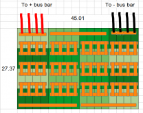
Based on the pic below, I'm thinking of making my own bus bars from onlinemetals.com - .25" x 1" silver-flashed copper bar:
 www.onlinemetals.com
The batteries and equipment are mounted/stored in a dedicated temperature controlled room inside my 30'x40' steel building.
I have 2x 600A bus bars from my current config that the 4x positive and 4x negative leads will attach then on to a 4/0 cable going to the 250A breaker in my Conext PDP.
So here come the questions:

Based on the pic below, I'm thinking of making my own bus bars from onlinemetals.com - .25" x 1" silver-flashed copper bar:
1/4" x 1" Copper Full Round Edge 110-H02 Silver Flash | Online Metals
View our full selection of 0.25" x 1" Copper Full Round Edge 110-H02 Silver Flash stock today on our website. Buy online with fast shipping direct to your door.
I have 2x 600A bus bars from my current config that the 4x positive and 4x negative leads will attach then on to a 4/0 cable going to the 250A breaker in my Conext PDP.
So here come the questions:
- Any issues with how I've planned to configure the bus bars and the stock I plan to use?
- Do I need to fuse the 4x leads (individually) going to the 600A bus bar? If so, what size fuse?
- I was planning to re-use 1/0 cable to connect from battery +/- to 600A bus bars (over kill, but have stock on hand)
- I'm trying to decide on a BMS - thoughts on this as it relates to this battery and my other equipment:
- Conext XW Pro 6846 Inverter
- Conext MPPT 60-150 CC (Qty 2)
- I also have the Connext Battery Monitor and Conext Gateway2, but I doubt I'm going to get integration with those
- Price isn't really the top consideration here - saving my investment, barring catastrophe and monitor-ability are the priorities.
- What relay(s) should I use with the new BMS - should I separate charge from invert if BMS can support that?
- I was thinking I'll need a custom enclosure/mount for the new battery. Should I plan to compress the cells horizontal (and vertical) to stave off cell expansion? I was planning to build this myself, but other's input is gladly accepted.

Ampster
Renewable Energy Hobbyist
For simplicity and to reduce connections I would make up four hole and eight hole bussbars and layout the cells differently in columns. I wish I could draw a picture but it may depend on how much room you have for columns and rows. If you go to this resource and look at any of the figure E diagrams and scale up you may get a picture of what I am saying. https://diysolarforum.com/resources/cell-configurations-for-12v-24v-and-48v-lifepo4-batteries.123/[*]Any issues with how I've planned to configure the bus bars and the stock I plan to use?
I would use one 4/0 cable from the center or end of a buss bar connected to a separate hole and fuse just that connection. I prefer not to use the small 6mm connections but rather 5/16" or 3/8" lugs. Are you actually loading that pack up to 600 Amps? If less you might be able to get by with 1/0 in open air.[*]Do I need to fuse the 4x leads (individually) going to the 600A bus bar? If so, what size fuse?
I would pick a BMS that can communicate with my inverter. I think others have found some that connect with Schneider equipment. It may have a separate on off switch that could be triggered by the BMS. I would also consider a KiloVac contactor. It may depend on your anticipated current whether there is a SSR that can handle 600 Amps.[/list].......
[*]I'm trying to decide on a BMS - thoughts on this as it relates to this battery and my other equipment:
Last edited:
FilterGuy
Solar Engineering Consultant - EG4 and Consumers
If you use silver flashed copper, make sure the silver is polished before assembly, The silver tarnish is a lot less conductive than copper or copper Oxide. Presumably, the silver will not tarnish where it is pressed against the terminals (and/or itself), but I can't be sure of that.I'm thinking of making my own bus bars from onlinemetals.com - .25" x 1" silver-flashed copper bar:
I generally just use the rectangular copper bar from online metals.... It is a lot cheaper.
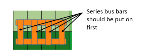
On the inner 'boxed' busbars, Put the serial bars down first. They are likely to be carying more of the current and therefor should be directly on the cell terminal pad. (The parallel bars will only carry enough current to keep the voltage equalized amoung the parallel cells).

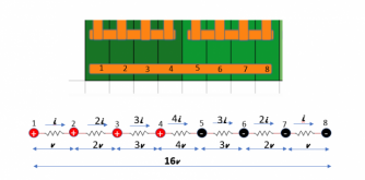
If Possible, I would use heaver duty bus bars on the long 8 hole busbars. This will help prevent voltage changes between the cells. To explain why, the following diagram models the resistance of the bus-bar, the current and voltage drops along the bus bar. (This modeling is a first order approximation. A better model would seperate the copper resistance from the connection resistance to each terminal). As you can see, in this model, the voltage drop across the whole busbar is 16 times the voltage drop between terminal 1 and 2.

The question then becomes: How big does this voltage actually get?
Lets assume that with the connections to the terminal pad and the copper you have .2 mOhm (.0002 ohm) resistance between any two adjacent terminals. Now lets assume you are pulling 100 amp total from the bank. The 100 Amps battery draw would show up between the positive and negative, so in this model 4i=100A. That means i is 25A. Consequently v is .0002ohm x 25A = .005V and the total drop from one end of the bar to the other is 16x.0025=.08V. (The voltage will increase/decrease linearly with current)
Is 0.2mOhm higher than reality? I don't know but .2mOhm is certainly not a large number.
Is .08V a killer? I don't know, but it is certainly getting in the range to think about.
The bottom line is that anything you can do to reduce the resistance on the long bus-bars is important in order to keep the voltage at the cells as similar as possible. Having a single bus-bar instead of stacking 2-hole factory bus-bars is a huge improvement (Far fewer connections). Making the single bus-bar extra thick/wide will help as well.
When you set this up, it would be interesting to put a sensitive voltmeter across the length of the long busbar and see what drop you get under a heavy load.
FilterGuy
Solar Engineering Consultant - EG4 and Consumers
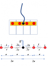
I assume the 4x leads are to try to keep things balanced between cells. I would make the 4-hole 'end' busbars extra heavy duty for the same reason I outlined for the 8-hole busbars above. This attacks the problem 'at the source'. However, as my model above shows, it can not totally eliminate it. If you make the busbar extra heavy duty and do like @Ampster suggested with a tap in the middle you should be 'good enough'
- Do I need to fuse the 4x leads (individually) going to the 600A bus bar? If so, what size fuse?
Note: see this for making busbars: https://diysolarforum.com/resources/diy-heavy-duty-distribution-bus-bar.71/
If you still want to do the 4 leads, the objective is to make sure the resistance is the same to any single cell, Consequently, you should make sure they are all the same length and bolt down to a heavy duty busbar on the other end. In fact, if your lugs are nice and flat on the top and bottom, you could double up the lugs on two or even one post:

Note: I have never recommended or considered putting 4 large lugs on one post before. I am not even sure I like the idea. It is not considered good practice to have more than a couple of lugs on a post. If you do this, make sure the faces of the lugs sit flat on each other and make a good connection. Also, make sure the bolt on the post fully threads onto the post.
Also, If you go with the 4 leads, don't do individual fuses. The variance on the resistance of each fuse would probably defeat the hole purpose of multiple leads.
FilterGuy
Solar Engineering Consultant - EG4 and Consumers
Doing similar modeling as for the 8 hole bus-bar you get this:If you make the busbar extra heavy duty and do like @Ampster suggested with a tap in the middle you should be 'good enough'

If we plug in the same assumptions of 100A and .2mOhm, there is only .01V (or less) difference between any two terminals.
shorawitz
Solar Enthusiast
For the bus bars, your suggestion of 4 hole and 8 hole bus bars - isn't that what the picture shows or am I missing the picture? Maybe a picture really does speak 1000 words. I used Libre Office Calc (M$ Excel alternative) to create that graphic.For simplicity and to reduce connections I would make up four hole and eight hole bussbars and layout the cells differently in columns. I wish I could draw a picture but it may depend on how much room you have for columns and rows.
I would use one 4/0 cable from the center or end of a buss bar connected to a separate hole and fuse just that connection. I prefer not to use the small 6mm connections but rather 5/16" or 3/8" lugs. Are you actually loading that pack up to 600 Amps? If less you might be able to get by with 1/0 in open air.
I would pick a BMS that can communicate with my inverter. I think others have found some that connect with Schneider equipment. It may have a separate on off switch that could be triggered by the BMS. I would also consider a KiloVac contactor. It may depend on your anticipated current whether there is a SSR that can handle 600 Amps.[/list]
The 4/0 cable suggestion makes sense. I was (kind of) cheaping-out by using the 1/0 cable I have, but less stress on the lugs is a very good point.
I've only really seen rumor for the compatible BMS and Schneider. Their implementation of Canbus (Xanbus) is supposed to be proprietary/encrypted. I was going to try to hack it to see if I could get something going, but work has been slamming me with other coding projects that I keep letting that one slip.
As far as anticipated current, I don't expect this battery to exceed 250A (but more likely will be <100A sustained for periods of time that are beyond 5 seconds.) 250A is the max of a single XW Pro for 5 seconds. When my "current" needs to increase, I'll add another battery and a second inverter to handle the increased load.
BTW, how did you arrive at 600A for load? If you're referring to my comment about the 600A common bus bars, I have those in my current config and I use those today to connect my BYD packs as 4 individual 48V batteries (2x 25.6V in series, that then connect to the 600A bus bars) fused (100A each) and switched (similar to Blue Sea 48V disconnect switch.) I set them up that way because at the time, these BYD's were pretty new to the off-grid community and I wanted the ability take a pair out of commission in case of issue with any one pack. Basically, my current setup is 16S4P. The 2 common bus bars I have now are similar to the Blue Sea Systems bus bars.
Good points all-in-all. I need to a different application to draw that battery and incorporate all of this thread's posters suggestions!
shorawitz
Solar Enthusiast
Do you think I could use something to polish the silver to retard tarnishing?If you use silver flashed copper, make sure the silver is polished before assembly, The silver tarnish is a lot less conductive than copper or copper Oxide. Presumably, the silver will not tarnish where it is pressed against the terminals (and/or itself), but I can't be sure of that.
Great advice. I'll add that to the list of changes to the diagram.I generally just use the rectangular copper bar from online metals.... It is a lot cheaper.
On the inner 'boxed' busbars, Put the serial bars down first. They are likely to be carying more of the current and therefor should be directly on the cell terminal pad. (The parallel bars will only carry enough current to keep the voltage equalized amoung the parallel cells).
View attachment 30064
Wow! A lot to digest there. I was looking at some online data regarding how/what to use for bus bars. I couldn't find any quantitative data on using thinner stacks of thinner copper vs thicker cross sections of bus bar. If I use 1/4" for the shorter inter-connects, should I just to 1/2" or will 3/8" work? Based on what I'm seeing at onlinemetals.coms, my only choice for those thicknesses are pure copper.If Possible, I would use heaver duty bus bars on the long 8 hole busbars. This will help prevent voltage changes between the cells. To explain why, the following diagram models the resistance of the bus-bar, the current and voltage drops along the bus bar. (This modeling is a first order approximation. A better model would seperate the copper resistance from the connection resistance to each terminal). As you can see, in this model, the voltage drop across the whole busbar is 16 times the voltage drop between terminal 1 and 2.
View attachment 30041
The question then becomes: How big does this voltage actually get?
Lets assume that with the connections to the terminal pad and the copper you have .2 mOhm (.0002 ohm) resistance between any two adjacent terminals. Now lets assume you are pulling 100 amp total from the bank. The 100 Amps battery draw would show up between the positive and negative, so in this model 4i=100A. That means i is 25A. Consequently v is .0002ohm x 25A = .005V and the total drop from one end of the bar to the other is 16x.0025=.08V. (The voltage will increase/decrease linearly with current)
Is 0.2mOhm higher than reality? I don't know but .2mOhm is certainly not a large number.
Is .08V a killer? I don't know, but it is certainly getting in the range to think about.
The bottom line is that anything you can do to reduce the resistance on the long bus-bars is important in order to keep the voltage at the cells as similar as possible. Having a single bus-bar instead of stacking 2-hole factory bus-bars is a huge improvement (Far fewer connections). Making the single bus-bar extra thick/wide will help as well.
When you set this up, it would be interesting to put a sensitive voltmeter across the length of the long busbar and see what drop you get under a heavy load.
shorawitz
Solar Enthusiast
Makes sense to KISS to keep resistance in check. So it sounds like I should add another hole to the +/- bus bars and use 4/0 all the way to the 250A breaker for "+" (in Conext PDP) and the shunt for "-".I assume the 4x leads are to try to keep things balanced between cells. I would make the 4-hole 'end' busbars extra heavy duty for the same reason I outlined for the 8-hole busbars above. This attacks the problem 'at the source'. However, as my model above shows, it can not totally eliminate it. If you make the busbar extra heavy duty and do like @Ampster suggested with a tap in the middle you should be 'good enough'
Note: see this for making busbars: https://diysolarforum.com/resources/diy-heavy-duty-distribution-bus-bar.71/
If you still want to do the 4 leads, the objective is to make sure the resistance is the same to any single cell, Consequently, you should make sure they are all the same length and bolt down to a heavy duty busbar on the other end. In fact, if your lugs are nice and flat on the top and bottom, you could double up the lugs on two or even one post:
View attachment 30070
Note: I have never recommended or considered putting 4 large lugs on one post before. I am not even sure I like the idea. It is not considered good practice to have more than a couple of lugs on a post. If you do this, make sure the faces of the lugs sit flat on each other and make a good connection. Also, make sure the bolt on the post fully threads onto the post.
Also, If you go with the 4 leads, don't do individual fuses. The variance on the resistance of each fuse would probably defeat the hole purpose of multiple leads.
Ampster
Renewable Energy Hobbyist
No, I was thinking of a staggered alternation of mostly 8 hole buss bars going horizontally but that would require unequal length 4/0 connections at some of the ends where 4 hole buss bars would have to connect to adjacent buss bars. That could introduce some slight different resistance at those connections that might offset the convenience and simplicity of construction. Based on the calculations of @FilterGuy that could be as much as 40 millivolts between each group of four. My BMS can compensate for that but most can't so my simplistic buss bar approach may not be worth it in terms of adding variations between cells. With variations of layout I think that could be eliminated and the only differences might be difference between the side to side versus the end to end terminal hole differences especially if you wanted to run thread rod horizontally between the rows. The advantage of your layout is the 4 buss bars would compensate for the resistance of that extra length between the holes.For the bus bars, your suggestion of 4 hole and 8 hole bus bars - isn't that what the picture shows or am I missing the picture?
shorawitz
Solar Enthusiast
I stand corrected!!!For simplicity and to reduce connections I would make up four hole and eight hole bussbars and layout the cells differently in columns. I wish I could draw a picture but it may depend on how much room you have for columns and rows. If you go to this resource and look at any of the figure E diagrams and scale up you may get a picture of what I am saying. https://diysolarforum.com/resources/cell-configurations-for-12v-24v-and-48v-lifepo4-batteries.123/
I would use one 4/0 cable from the center or end of a buss bar connected to a separate hole and fuse just that connection. I prefer not to use the small 6mm connections but rather 5/16" or 3/8" lugs. Are you actually loading that pack up to 600 Amps? If less you might be able to get by with 1/0 in open air.
I would pick a BMS that can communicate with my inverter. I think others have found some that connect with Schneider equipment. It may have a separate on off switch that could be triggered by the BMS. I would also consider a KiloVac contactor. It may depend on your anticipated current whether there is a SSR that can handle 600 Amps.[/list]
I just found this PDF on Schneider's web site:
I guess this puts my Conext Battery Monitor on the chopping block. All I need is a CAN or RS485 compatible BMS.
Ampster
Renewable Energy Hobbyist
You sound like you may have more experience than I on integrating CAN BUS messages. I do know that Victron has done an integration with an Orion BMS using a display that speaks translates CAN messages to the Victron proprietary protocol. I seem to recall one other with an Orion. I will look through the forum and see if I can find it.I guess this puts my Conext Battery Monitor on the chopping block. All I need is a CAN or RS485 compatible BMS.
I have an Orion BMS and love it. Orion has a lot of documentation about their CAN messages and you can actually see the CAN messages on the Orion PC interface program. My issue has been that Outback has not been open about that on the inverter side.
Similar threads
- Replies
- 17
- Views
- 837
- Replies
- 105
- Views
- 9K
- Replies
- 8
- Views
- 2K
- Replies
- 20
- Views
- 2K
- Replies
- 65
- Views
- 5K


