


You are using an out of date browser. It may not display this or other websites correctly.
You should upgrade or use an alternative browser.
You should upgrade or use an alternative browser.
Has anyone used that Chinese Capacity Tester Will used on his video?
- Thread starter TommyHolly
- Start date
TommyHolly
New Member
- Joined
- Jun 24, 2021
- Messages
- 207
I just purchased the 180w version with the color screen. (Although I’m a little confused since it has 4 plugs… A+ A- V+ V-… which one do I use for the capacity test?)If you can afford it, i'd go the 180w version for $10 more.
Also depends on how soon you need it. Coming from Aliexpress means China, which means likely at least a month to get to you.
That voltage drop could be due to high cell internal resistance (old and used cell), or poor wiring. Hard to tell.
i ordered it off of Amazon and it should be at the Florida shipping warehouse by Thursday.
If there was high internal resistance in one of the cells, shouldn’t I have seen a large drop in the resting voltage tests?
RCinFLA
Solar Wizard
- Joined
- Jun 21, 2020
- Messages
- 3,565
The V+ and V- are for remote voltage sensing. By connecting V+/- to battery terminals (just need small wires) you avoid the wiring voltage drop on the high current load wires going to A+/-. A+ and A- are the actual load.
Makes the battery voltage reading more accurate.
If doing low current loading you can just jumper V+ to A+ and V- to A-.
Makes the battery voltage reading more accurate.
If doing low current loading you can just jumper V+ to A+ and V- to A-.
Last edited:
TommyHolly
New Member
- Joined
- Jun 24, 2021
- Messages
- 207
Good catch! I can’t read where it said it went down to 2.77v? The smallest I saw was 2.85v when he started the test. The clips I used were supplied by the Chinese company, but it was 14AWG wire so not that thin and it was connected well to the alligator clips. I’m not so sure I would have gotten a different result with different clips.Also in the video you can see the rest leads were changed out and larger allagator clips were used. But, during single cell testing the voltage did drop to 2.77, so imagine if you had crappier connections the test rig would just read lower voltages.
During my test, when I tried to test it at 0.2C (20A), my cell immediately dropped down lower than the 2.6v low cutoff and displayed the warning then stopped the test. I was only able to complete the test by continuously turning down the amperage each time I received that warning. I started at 15A and ended up at 1A after it stopped about 10 times.
I want to test one of the best cells I have and see if the results are different. But do you think I did the test correctly?
TommyHolly
New Member
- Joined
- Jun 24, 2021
- Messages
- 207
A
So that lower voltage reading I got from the Capacity Tester which was much lower than my multimeter… that was the result of using the same wire to test Ah capacity as it was voltage.
So basically you are saying when I perform the next test using the new 180w capacity tester I purchased, it will be more accurate and display the correct voltage because it’s using different wires.
I’m not sure what counts as “low current” testing? But I don’t think I’d want to jump those together because the problem I was having was the test was lowering my voltage under the 2.6v low cutoff limit immediately. I’d want the correct voltage displayed if at all possible.
Thanks!! Great info.
Ahhh ok nice!!The V+ and V- are for remote voltage sensing. By connecting V+/- to battery terminals (just need small wires) you avoid the wiring voltage drop on the high current load wires going to A+/-. A+ and A- are the actual load.
Makes the battery voltage reading more accurate.
If doing low current loading you can just jumper V+ to A+ and V- to A-.
So that lower voltage reading I got from the Capacity Tester which was much lower than my multimeter… that was the result of using the same wire to test Ah capacity as it was voltage.
So basically you are saying when I perform the next test using the new 180w capacity tester I purchased, it will be more accurate and display the correct voltage because it’s using different wires.
I’m not sure what counts as “low current” testing? But I don’t think I’d want to jump those together because the problem I was having was the test was lowering my voltage under the 2.6v low cutoff limit immediately. I’d want the correct voltage displayed if at all possible.
Thanks!! Great info.
TommyHolly
New Member
- Joined
- Jun 24, 2021
- Messages
- 207
Hey thanks!As someone else also mentioned, the leads may have a lot of resistance when under load causing a voltage drop. They may also be fine, but by measuring where they connect to the board, you can rule out that possibility. If you measure there and it's the same (or very close) reading as what the board is reporting, you know the leads are the problem.
I never considered testing at the board for a different voltage.
Example:
So if I measure the battery cell terminals and come up with 3.0v and then measure at the circuit board of the capacity tester, and come up with 2.7v then I should suspect the alligator clips and swap out the clips for something better.
TommyHolly
New Member
- Joined
- Jun 24, 2021
- Messages
- 207
That’s a great idea!!That or the alligator clips, put proper ring terminals on. If the load tester thinks the cell voltage is 2.6, but you’ve proven otherwise, it’s not the cell that you should be worried about.
I have ring terminals and thicker gauge wire I can use. The next few tests I’ll use the ring terminals.
Im learning so much from you guys. It all makes sense.
TommyHolly
New Member
- Joined
- Jun 24, 2021
- Messages
- 207
How would you test PV panels using one of these capacitor testers and why? I usually just hook up a DC Amp meter around the cord for the panel to see what it’s putting out.If you get one make sure it includes CV function. The one with adjustment knobs do not have CV.
CV is useful for testing PV panels.
DerpsyDoodler
Solar Addict
- Joined
- Jan 10, 2021
- Messages
- 2,247
to see voltage drop under load, i imagine.
Bud Martin
Solar Wizard
- Joined
- Aug 27, 2020
- Messages
- 4,844
I do shorted circuit current test using clamp on DCA meter.How would you test PV panels using one of these capacitor testers and why? I usually just hook up a DC Amp meter around the cord for the panel to see what it’s putting out.
HOBOTECH uses the load test to test the PV panel, but make sure the PV Voltage does not exceed the tester input Voltage limit.
For example, see the test at 5:00 mark.
At 3:00 mark.
RCinFLA
Solar Wizard
- Joined
- Jun 21, 2020
- Messages
- 3,565
With Constant Voltage mode (CV) you are loading the panel with a clamped voltage level.
At CV less than about half Vmp or lower you will read Isc for given illumination level. As you adjust CV higher, adjust for maximum power on load tester readout. This is Vmp for given illumination level and panel temperature. Continue to raise CV higher until current drops to near zero. This is Voc for given panel temperature.
Panel current and wattage readout will accompany voltage clamp level settings adjustment. This is the same curves you see on the panel spec sheets, be it perhaps at a different panel temperature depending on your environment.
The load tester limits are 180W, 200v, 20 amps. The voltage x load current is limited to less then the 180 watt rating as the heat sink will get too hot. I believe it has a temp sensor to shut itself down if it does get too hot.
You may be able to test a higher wattage panel then 180 watts, just have to do it quickly before load heatsink gets too hot. The one I have does not electronically limit the 180 watt load level but it will shut down if it gets too hot. Only usually an issue near peak power output Vmp of panel. Isc and Voc measurements are not producing much power.
For most panels, Vmp is about 85% of Voc. Imp is about 95% of Isc. This relationship falls apart at lower illumination levels where panel shunt leakage starts to become a significant factor.
Last edited:
Texas-Mark
Solar Addict
- Joined
- Aug 4, 2021
- Messages
- 1,284
Example:
So if I measure the battery cell terminals and come up with 3.0v and then measure at the circuit board of the capacity tester, and come up with 2.7v then I should suspect the alligator clips and swap out the clips for something better.
Yep. As someone else mentioned, ring terminals would be better.
TommyHolly
New Member
- Joined
- Jun 24, 2021
- Messages
- 207
Interesting,I do shorted circuit current test using clamp on DCA meter.
HOBOTECH uses the load test to test the PV panel, but make sure the PV Voltage does not exceed the tester input Voltage limit.
For example, see the test at 5:00 mark.
At 3:00 mark.
But why Is he testing the solar panels? (Or is that you?) He said they are pulling 140w out of 180w… so the panels aren’t getting what he expected?
I like how his logo “Hobotech” looks like ROBOTECH… I was a big fan of that show and the books.
Bud Martin
Solar Wizard
- Joined
- Aug 27, 2020
- Messages
- 4,844
Panel spec is based on testing in the lab with calibrated test equipment.
TommyHolly
New Member
- Joined
- Jun 24, 2021
- Messages
- 207
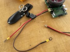
I removed the old leads, bought some 10 gauge oversized thick wire, installed ring terminals, and lightly sanded them all down with 2000 grit sandpaper to remove any corrosion due to the humid Panama air.That or the alligator clips, put proper ring terminals on. If the load tester thinks the cell voltage is 2.6, but you’ve proven otherwise, it’s not the cell that you should be worried about.
This should be good right?
Attachments
TommyHolly
New Member
- Joined
- Jun 24, 2021
- Messages
- 207
O
I should be good to go correct?
Ok, I removed the 12 gauge factory alligator clips and bought some oversized 10 gauge thick wire. I connected ring terminals and then lightly sanded the connectors to remove any corrosion from the humid Panama air. I also installed a 30A fuse in line in case the tester unit blows up. (I heard here when they fail, it’s a direct short and the battery can start on fire.)From the pictures, you're seeing a voltage drop across the leads due to the load.
This is why the newer tester model has 2 separate leads for voltage sensing.
Oversize all your cables. Make sure there's solid connection between the battery and cables, and the tester unit.
When draining a large current from a small battery, you'll likely see significant voltage drop anyhow, but it shouldn't be as big as you're seeing unless the battery is bad.
Change the leads from the default factory supplied ones, as they can be really shitty with high resistance.
With new leads and solid connection points, if there's still a drop then buy the newer testing unit.
I should be good to go correct?
Attachments

Texas-Mark
Solar Addict
- Joined
- Aug 4, 2021
- Messages
- 1,284
Looks good. Still be sure to check the voltage at both the battery and the tester if the there is any discrepancy.
TommyHolly
New Member
- Joined
- Jun 24, 2021
- Messages
- 207
I purchased and ordered the new 4-wire remote voltage sensing version but it won't be here until next week. I checked the resistance of the 30A in-line fuse and found it was 0 ohms. Do you think there will be a problem if I try to test the capacity with this in-line fuse on the old 150w Capacity tester? I figured that as long as the voltage at the tester is close to the voltage at the battery, then I should be ok? (I won't find out until tomorrow because the batteries are locked up in a workshop here at the Marina.)Check the resistance of fuse does not defeat the lower resistance wiring. With four wire remote voltage sensing version having an inline fuse would be okay.
Similar threads
- Replies
- 5
- Views
- 310
- Replies
- 4
- Views
- 393
- Replies
- 26
- Views
- 1K