diy solar

diy solar

Has anyone used that Chinese Capacity Tester Will used on his video?

To make sure my yellow voltmeter isn’t bad, I used a second red Uni-T voltmeter which matched the results of the yellow one.
Replace the wires, those that come with the device are not going to work at 20 amps, thus the voltage drop is excessive.
10 gauge wire, with crimp ring terminals for the battery end and spade terminals for the tester end, work well, then set the disconnect voltage to 2.3v.

If you use the supplied "cables", you won't get it to work as you have noticed.
 
I just purchased the 180w version with the color screen. (Although I’m a little confused since it has 4 plugs… A+ A- V+ V-… which one do I use for the capacity test?)

i ordered it off of Amazon and it should be at the Florida shipping warehouse by Thursday.

If there was high internal resistance in one of the cells, shouldn’t I have seen a large drop in the resting voltage tests?
You should read my findings of that tester. Basically, it runs very hot at maximum capacity.


You still need to use adequate wiring to run it at any real load.
 
When brand new they tested at around 115Ah because the original owner was bragging how the system was 1,400Ah. I couldn’t figure out how he came to that number until I saw that CALB cells usually test at 115Ah or so for the first 20 cycles even though they eventually rest at 100Ah.
So far the two worst cells are at 93 & 94Ah so I’m doing good.
Cell manufacturers usually recommend to stop using them when they get to 70% or less.
Life cycle rating is determined by how many cycles it takes to get to 80% of capacity.

When testing cells, best to stick to the 3.65v to 2.5v start and stop. Hard to compare when you use different voltages.
 
Some of these load testers use IRFP240A MOSFET for load device. Some have the IRFP250A or their Chinese clones.
The recent Atorch DL24 I bought has the better IRFP260A device.

Depending on device used, the Rds_ON of MOSFET will limit their minimum pull down voltage at 20 amps from 2.0v to 3.6v.
Add a little extra for PCB runners and connector terminal, before you get to your wiring loss.

When loading MOSFET gets hot its Rds_ON rises, by about 130% of room temp at 65 degs C making min pull down voltage higher.

Should avoid IRFP240A
IRFP240A -> Rds_ON at 25degs C = 0.14 ohms, x 20 A = 2.8v + PCB drop + connector drop + wire drop.
IRFP240A -> Rds_ON at 65degs C = 0.18 ohms, x 20 A = 3.6v + PCB drop + connector drop + wire drop.

Satisfactory results with IRFP250A, if wiring drop is not too great

IRFP250A -> Rds_ON at 25degs C = 0.08 ohms, x 20 A = 1.6v + PCB drop + connector drop + wire drop.
IRFP250A -> Rds_ON at 65degs C = 0.10 ohms, x 20 A = 2.0v + PCB drop + connector drop + wire drop.

----------------------------------------------------------------------------------------------------------------------------
Best replacement device, maintaining 200v max breakdown.

IRFP260A -> Rds_ON at 25degs C = 0.04 ohms, x 20 A = 0.8v + PCB drop + connector drop + wire drop.
IRFP260A -> Rds_ON at 65degs C = 0.05 ohms, x 20 A = 1.0v + PCB drop + connector drop + wire drop.

If the device cannot make the terminate discharge voltage you set with 20 amp load it will continue to discharge battery until cell current drops off enough for the voltage across the Rds_ON to make your terminate trip voltage. This will not be the intended discharge point on cell you want.
 
Last edited:
Some of these load testers use IRFP240A MOSFET for load device. Some have the IRFP250A or their Chinese clones.
The recent Atorch DL24 I bought has the better IRFP260A device.

Depending on device used, the Rds_ON of MOSFET will limit their minimum pull down voltage at 20 amps from 2.0v to 3.6v.
Add a little extra for PCB runners and connector terminal, before you get to your wiring loss.

When loading MOSFET gets hot its Rds_ON rises, by about 130% of room temp at 65 degs C making min pull down voltage higher.

Should avoid IRFP240A
IRFP240A -> Rds_ON at 25degs C = 0.14 ohms, x 20 A = 2.8v + PCB drop + connector drop + wire drop.
IRFP240A -> Rds_ON at 65degs C = 0.18 ohms, x 20 A = 3.6v + PCB drop + connector drop + wire drop.

Satisfactory results with IRFP250A, if wiring drop is not too great

IRFP250A -> Rds_ON at 25degs C = 0.08 ohms, x 20 A = 1.6v + PCB drop + connector drop + wire drop.
IRFP250A -> Rds_ON at 65degs C = 0.10 ohms, x 20 A = 2.0v + PCB drop + connector drop + wire drop.

----------------------------------------------------------------------------------------------------------------------------
Best replacement device, maintaining 200v max breakdown.

IRFP260A -> Rds_ON at 25degs C = 0.04 ohms, x 20 A = 0.8v + PCB drop + connector drop + wire drop.
IRFP260A -> Rds_ON at 65degs C = 0.05 ohms, x 20 A = 1.0v + PCB drop + connector drop + wire drop.

If the device cannot make the terminate discharge voltage you set with 20 amp load it will continue to discharge battery until cell current drops off enough for the voltage across the Rds_ON to make your terminate trip voltage. This will not be the intended discharge point on cell you want.
Yes, unless you desolder them, you have no way of knowing what part was used.
 
Eagerly awaiting the EBC-A20 ( as tested by Andy@Off Grid Garage ) to arrive. The only problem is that it is limited to max 30v , so the 48v 100ah battery that I just build will have to be tested in two stages of 24v each. Will report results.
 
Eagerly awaiting the EBC-A20 ( as tested by Andy@Off Grid Garage ) to arrive. The only problem is that it is limited to max 30v , so the 48v 100ah battery that I just build will have to be tested in two stages of 24v each. Will report results.
It looks like you need to watch out for bad power supply that comes with unit, the output went up to 27V on Andy's video.
 
What Ah capacity am I looking for?

These are 100Ah cells which are 6 years old so if I get anything less than that, are they bad? Or is anything over 93Ah good?? 95Ah?? 100Ah only?
The big variable is how may times they were cycled, and at what rate / depth of discharge.

Most LiFePO4 cell manufacturers use 80% capacity left as the baseline for end-of-life. So anything over 80ah is still acceptable to use. The lower the capacity, the more wear and tear on the cells. Also, higher internal resistance generally means an older, used, cell.

Some people buy used cells that have less than 80% capacity left and use them down to 50-60% (BatteryHookup sells out of heavily worn cells surprisingly fast) , I haven't seen anything to indicate that they become dangerous after a certain point. As long as they weren't abused, I would personally have no problem using cells until they don't work for my application anymore.

IMHO, if the remaining capacity meets your needs, then they are good cells. If it doesn't, you can put them on eBay with as much info as you have on them, and use the funds towards new batteries.
 
Yes, but a 7812 is a 79 cent part. I'd just run it off a 12v power supply.
The 7812 is for regulated power supply to run the controller, the 19V is being used for charging, that is why they supply it with 60W power supply, right now we do not know if the charging section is damaged or not.
 
The big variable is how may times they were cycled, and at what rate / depth of discharge.

Most LiFePO4 cell manufacturers use 80% capacity left as the baseline for end-of-life. So anything over 80ah is still acceptable to use. The lower the capacity, the more wear and tear on the cells. Also, higher internal resistance generally means an older, used, cell.

Some people buy used cells that have less than 80% capacity left and use them down to 50-60% (BatteryHookup sells out of heavily worn cells surprisingly fast) , I haven't seen anything to indicate that they become dangerous after a certain point. As long as they weren't abused, I would personally have no problem using cells until they don't work for my application anymore.

IMHO, if the remaining capacity meets your needs, then they are good cells. If it doesn't, you can put them on eBay with as much info as you have on them, and use the funds towards new batteries.
I just worry about getting dendrites when they get old and have a few thousand cycles, but I am also the type to use a class T fuses and a quality breaker. Different people have different ideas about acceptable risk, I am one of those belt and suspenders people.
 
The 7812 is for regulated power supply to run the controller, the 19V is being used for charging, that is why they supply it with 60W power supply, right now we do not know if the charging section is damaged or not.
Thanks, I don't have that model and didn't know. The 40 amp cell tester I have uses a decent quality 5v, 300 watt switching supply internally.
 
It looks like you need to watch out for bad power supply that comes with unit, the output went up to 27V on Andy's video.
Thanks Bud: Somehow I missed this video but in a later one I saw him receiving the voltage regulator 7812 but I was unaware thar it was for the tester. Wondering if the voltage spike was generated by his inverter system running the garage ? Those laptop power supplies are normally quite robust.
 
Last edited:
Watched his follow-up video. Looks like the plug-in power supply crapped out. Strange that there is no fuse in the cct with the 7812 regulator. Such a cheap component could have protected the battery tester. As soon as mine arrives I am going to put a zener diode / fuse combination at the input.
 
Cell manufacturers usually recommend to stop using them when they get to 70% or less.
Life cycle rating is determined by how many cycles it takes to get to 80% of capacity.

When testing cells, best to stick to the 3.65v to 2.5v start and stop. Hard to compare when you use different voltages.
I replaced the load wires with very thick 10AWG wires which was the largest the device could take and made sure they were the same length at 10” inches. I placed ring terminals on the end.

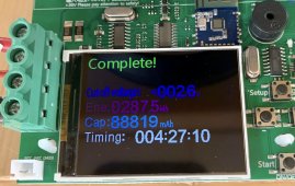
The tests so far have shown that all the batteries are around 85-89Ah. I’m pretty disappointed. I was hoping for more since the old 150W tester was providing higher Ah numbers.
 

Attachments

  • EE9FF72C-AA26-4446-BF30-C5D5D5362094.jpeg
    EE9FF72C-AA26-4446-BF30-C5D5D5362094.jpeg
    284.2 KB · Views: 7
Replace the wires, those that come with the device are not going to work at 20 amps, thus the voltage drop is excessive.
10 gauge wire, with crimp ring terminals for the battery end and spade terminals for the tester end, work well, then set the disconnect voltage to 2.3v.

If you use the supplied "cables", you won't get it to work as you have noticed.
I just saw the disconnect voltage at 2.3v??
I was told many times not to go below 2.6 or 2.5v at a maximum. (Will says the same in his video)
In practice with the tester, once the battery went below 2.8v it immediately dropped off the cliff. I only got an extra 1 minute of testing going from 2.7v to 2.6v for example. So going down to 2.3v wouldn’t provide much of a difference. I don’t want to ruin my batteries any more than the previous boat owner did. I’m still fixing his mistakes.
 
Hey
The big variable is how may times they were cycled, and at what rate / depth of discharge.

Most LiFePO4 cell manufacturers use 80% capacity left as the baseline for end-of-life. So anything over 80ah is still acceptable to use. The lower the capacity, the more wear and tear on the cells. Also, higher internal resistance generally means an older, used, cell.

Some people buy used cells that have less than 80% capacity left and use them down to 50-60% (BatteryHookup sells out of heavily worn cells surprisingly fast) , I haven't seen anything to indicate that they become dangerous after a certain point. As long as they weren't abused, I would personally have no problem using cells until they don't work for my application anymore.

IMHO, if the remaining capacity meets your needs, then they are good cells. If it doesn't, you can put them on eBay with as much info as you have on them, and use the funds towards new batteries.
Hey thanks!
The battery cells have all been testing at around 85Ah to 89Ah. So as long as they are above 80, it sounds like I’m still good to go if I want to reinstall them.

I’m making a list of the Ah Capacity test results. People here told me to pair the best with the worst. So #1 with #48. #2 with #47 and so on…
 
I just saw the disconnect voltage at 2.3v??
I was told many times not to go below 2.6 or 2.5v at a maximum. (Will says the same in his video)
In practice with the tester, once the battery went below 2.8v it immediately dropped off the cliff. I only got an extra 1 minute of testing going from 2.7v to 2.6v for example. So going down to 2.3v wouldn’t provide much of a difference. I don’t want to ruin my batteries any more than the previous boat owner did. I’m still fixing his mistakes.
Yes, there is really no capacity down that low. Unless it is a 4 wire tester, which yours is from the pictures, you must use a lower setting to account for the voltage drop. In your case, 2.5v is the correct voltage to use. So, 6 years old and still 89% capacity. Not bad.
 
Back
Top