brandnewb
Going for serious. starting as newb
WARNING. here be dragons. Playing with mains voltage is not recommended and could be fatal if done wrong!
I really could use some pointers here reaching my main goal of getting 3.6VDC at 140 amps.
Background is that I have a few 3.2V 280Ah Lifepo4 prismatic cells and before I get more of those I'd like to see if they can really charge at .5C i.e. 140 amps as their specs state.
The reason I'd like to see that is because I am planning to build such an overkill in power generating stuff around the house that my (future) battery bank should never become a bottleneck. It would be a shame if I purchase many more of those cells only to find out later down the line that the seller has been untruthful regarding their capabilities.
Another reason is simply to see if the seller is to be trusted so I can also purchase other items from them.
I'd like to start testing a single cell so that I do not damage all of them if something goes wrong.
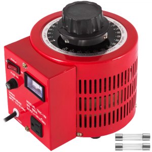
I have considered using a variac to transform my mains 230VAC to 3.6VAC and then using a bridge rectifier to convert it to DC. The problem with that is that the variac's that I can afford are well below the 140 amps output goal.
I have considered an arc welding transformer but I was informed that those drop the amps once a bridge has been formed or something to that extend. I did not really understand what was told to me.
As I did not find any other things to try I landed on a DIY solution.
My first attempt was a misguided one when I still had even less knowledge about the subject than I have now. It was a rather small 3d printed transformer core using ferromagnetic filament.

On the primary side there are 63 winds of 1mm enameled copper wire. On the secondary side a single wind of 8mm (50mm2) wire.
This does not work and leads to the circuit breaker tripping. The material used for the core is not magnetically permeable enough I guess and the winds on the primary side are far too few.
So now I'll try again with a rather large (is it or should I go larger? Soon enough I can print really big objects with a huge diameter) torodial core using an iron filled resin I am going to make.
below is one half of the mold to hold the resin.

The resin will be heat resistant and loaded with iron dust, but not so much so that it becomes electrically conductive. It will be close to the magnetic permeability as regular iron would be I recon although I am nto sure how to test that yet. If anyone knows I would love to learn that.
Then the primary coil will consist of 630 winds of 1mm enameled copper wire and the secondary coil will consist of 10 turns of 8mm wire.
Shall I simply hook it up to the mains power and see what happens or should I first get a variac and see what happens when I apply a much lower voltage to the primary coil first and then gradually ramp up the voltage if things seem to work.
Does anyone have any other suggestions on how to get 3.6VDC at 140 amps?
I really could use some pointers here reaching my main goal of getting 3.6VDC at 140 amps.
Background is that I have a few 3.2V 280Ah Lifepo4 prismatic cells and before I get more of those I'd like to see if they can really charge at .5C i.e. 140 amps as their specs state.
The reason I'd like to see that is because I am planning to build such an overkill in power generating stuff around the house that my (future) battery bank should never become a bottleneck. It would be a shame if I purchase many more of those cells only to find out later down the line that the seller has been untruthful regarding their capabilities.
Another reason is simply to see if the seller is to be trusted so I can also purchase other items from them.
I'd like to start testing a single cell so that I do not damage all of them if something goes wrong.
I have considered using a variac to transform my mains 230VAC to 3.6VAC and then using a bridge rectifier to convert it to DC. The problem with that is that the variac's that I can afford are well below the 140 amps output goal.
I have considered an arc welding transformer but I was informed that those drop the amps once a bridge has been formed or something to that extend. I did not really understand what was told to me.
As I did not find any other things to try I landed on a DIY solution.
My first attempt was a misguided one when I still had even less knowledge about the subject than I have now. It was a rather small 3d printed transformer core using ferromagnetic filament.
On the primary side there are 63 winds of 1mm enameled copper wire. On the secondary side a single wind of 8mm (50mm2) wire.
This does not work and leads to the circuit breaker tripping. The material used for the core is not magnetically permeable enough I guess and the winds on the primary side are far too few.
So now I'll try again with a rather large (is it or should I go larger? Soon enough I can print really big objects with a huge diameter) torodial core using an iron filled resin I am going to make.
below is one half of the mold to hold the resin.
The resin will be heat resistant and loaded with iron dust, but not so much so that it becomes electrically conductive. It will be close to the magnetic permeability as regular iron would be I recon although I am nto sure how to test that yet. If anyone knows I would love to learn that.
Then the primary coil will consist of 630 winds of 1mm enameled copper wire and the secondary coil will consist of 10 turns of 8mm wire.
Shall I simply hook it up to the mains power and see what happens or should I first get a variac and see what happens when I apply a much lower voltage to the primary coil first and then gradually ramp up the voltage if things seem to work.
Does anyone have any other suggestions on how to get 3.6VDC at 140 amps?

")