You can use an ohm meter to see if coils of a transformer are isolated. Usually, each coil is isolated from others and has two leads. External to the windings, two coils might be connected in series, or in parallel (need to be same number of turns). Occasionally, two windings might already be connected in series with just 3 leads coming out.
Without anything connected to toroid transformer, measuring voltage in and out gives ratio of turns.
In the guy's video, with a 12V transformer, he connected a 12V car head lamp in series. That way if your DUT (device under test) doesn't have enough impedance to keep current low enough, voltage drops across the lamp and maximum current is what the lamp would draw.
The variacs I've seen go some percentage above input voltage. Yours has a meter up to 300V. 25% would be 75V from variac into toroid. You haven't indicated what voltage ratio toroid has. Open-circuit, that is. "150 mV" is its output pulled down with the short circuit loading it.
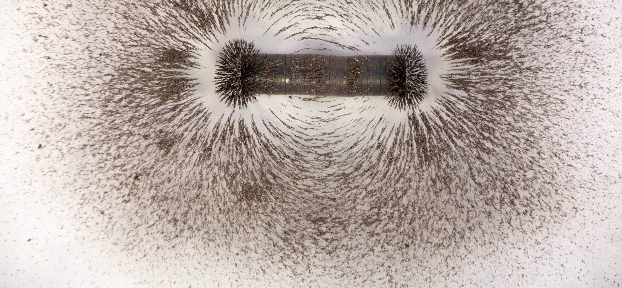
Your DUT has a coil diameter (about 2.5 cm) and number of turns (about 100?). Loosely space, so without core most magnetic field would leak out. You could calculate inductance assuming a uniform solenoid. Calculate AC impedance (reactance) at 50 Hz. Calculate current vs. voltage.
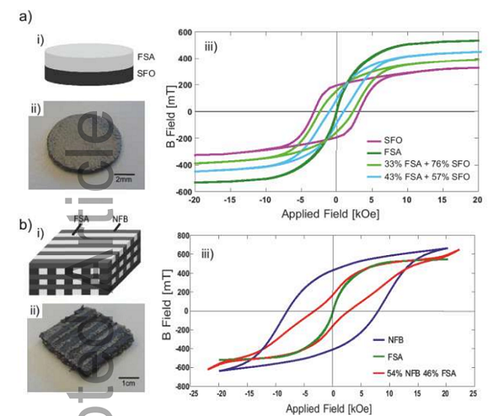
Measured with/without core material should give an indication of relative permeability.
Without a plumbing "T" to fill from, I would imagine there are airgaps without powder. But that probably isn't the biggest problem, rather the relative permeability being low.
It seems annealing is performed on magnetic material after they are formed. We've go some quotes for Mu-metal shields, which are to be formed by drawing or welding, then annealed. Working metal or sudden cooling results in small grains. Annealing grows large grains. If large grains make higher magnetic permeability, your powder is many tiny grains.
Iron powders relative permeability 2000 to 6000
This article & chart are a look at magnetic permeability. If you're struggling to get a quick response to an applied current in your product, try raising permeability. Let’s look at how different tiers of iron powder materials -- and the strong permeability of iron powder -- boost part performance.

www.horizontechnology.biz
Cores made from iron powder, 35 to 75
4 to 75
Sintered metal cores (metallurgical bond between particles) and "soft metallic composites" (no metallurgical bond, just interlocking shapes and dielectrics sticking together)
Trends in auto & other industries have spiked demand for magnetic materials. Today, soft magnetic composite is the answer. Here are SMC's greatest traits:
www.horizontechnology.biz
Is your iron powder intended for making magnets, or for sintering to use in other applications?


")
 www.conrad.nl