diy solar

diy solar

MPP LV6548 Ground/Neutral Safety?

so on layman terms, I would have a male and female outlet/inlet with a short jumper cord to connect them together to be on grid power and the inverter would have a male on the input and a female on the output and when I want inverter power I would unplug the jumper cord and plug the inverter in?
Yes
 
No
That breaker feeds those two wires, which feeds the bottom bus.
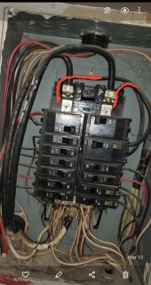
Oh, so the breaker sends power through the wires up towards the main lugs and thats where the bottom buss lugs are? I was thinking the power went the other direction and basically was back feeding through the breakers into the buss
 

Attachments

  • Screenshot_20220313-134312_Gallery.jpg
    Screenshot_20220313-134312_Gallery.jpg
    439.8 KB · Views: 1
That makes sense, an electrician should be able to do that for fairly cheap, no need to use my transfer switch, wanted to use it since I already owned it but if I can use a cord then even better, would just need to do all of this in my basement which would be about a 8 foot run
 
Oh, so the breaker sends power through the wires up towards the main lugs and thats where the bottom buss lugs are? I was thinking the power went the other direction and basically was back feeding through the breakers into the buss
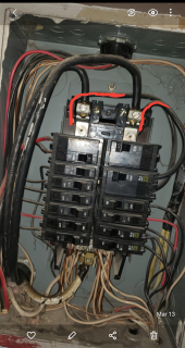
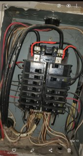
I see two pairs of breakers in the bottom section that have red and black wires. Those could be multiwire branch circuits (MWBC). If they are, you cannot have 120V from the inverter to both red and black wires because you will overload the neutral of the MWBC. Breakers should also be ganged if they feed a MWBC.

1647205033979.png
 

Attachments

  • 1647204986061.png
    1647204986061.png
    100.5 KB · Views: 2
I see two pairs of breakers in the bottom section that have red and black wires. Those could be multiwire branch circuits (MWBC). If they are, you cannot have 120V from the inverter to both red and black wires because you will overload the neutral of the MWBC. Breakers should also be ganged if they feed a MWBC.

View attachment 87213
Nice catch.
 
Multi-wire branch circuits are two hots and a shared neutral, in a single cable. The two circuits can share the single neutral because they are on different sides of the split phases.
When you combine the two hots from the inverter, this will overload the neutral in these cables.
You need to make sure that you are using both circuits of these cables, at the same time.
So it would have 3 wires in the romex plus a ground
 
Last edited:
Multi-wire branch circuits are two hots and a shared neutral, in a single cable. The two circuits can share the single neutral because they are on different sides of the split phases.
When you combine the two hots from the inverter, this will overload the neutral in these cables.
You need to make sure that you are using both circuits of these cables, at the same time.
I just looked and yes there are 4 wires in each of the romex, was doing some reading and apparently it should be on a double pull breaker but mine aren't nor are the breakers tied together so they trip simultaneously, im not even sure why its wired this way since its just a house and not a large building, does this mean I can't use a cord set, transfer switch or even use an inverter like I am trying to do?
 
I just looked and yes there are 4 wires in each of the romex, was doing some reading and apparently it should be on a double pull breaker but mine aren't nor are the breakers tied together so they trip simultaneously, im not even sure why its wired this way since its just a house and not a large building, does this mean I can't use a cord set, transfer switch or even use an inverter like I am trying to do?
It just means that you can't use both circuits in those cables, at the same time. While you are combining the two 120v sides into one.
 
Find out what they feed. It might be possible to combine them into one circuit per cable.
 
It just means that you can't use both circuits in those cables, at the same time. While you are combining the two 120v sides into one.
Watching Mike holt videos in it now, still confused though, looks like bad stuff can happen with this type of wiring, what do you mean can't use both circuits in the cables at same time,
 
Watching Mike holt videos in it now, still confused though, looks like bad stuff can happen with this type of wiring, what do you mean can't use both circuits in the cables at same time,
The neutral is not large enough to carry two circuits, on the same phase.
 
The neutral is not large enough to carry two circuits, on the same phase.
So I need to come up with a different way to connect my inverter? I didn't think this many worms could fit in a tiny can, the more I learn the more I get confused
 
Back
Top