diy solar

diy solar

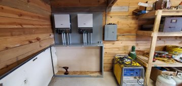
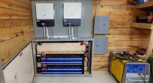
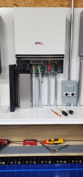
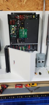
4 MPP LV6548 / 30 kW EVE 304ah LiFePO4 battery/ 14 kW PV array

Is it a correct assumption that you are wiring 2s4p there?

Based on Voc and Isc of 85.6v and 6.43a (per panel), which would come up to 171.2v (2s) and 25.72a (4p), not calculating in coldest temperature compensation.

What I am not understanding (it's hard to see where exactly all your wires are drawn, so based on assumption of 2s4p), where are you getting the 144v and 12a from (for the left 4 panels and the right 4 panels?

The Voc should be fine there at 171.2v, but if the Isc will really be at 25.72a, we've heard MPP Solar Support say to another forum member that 18a is rated PV input amps, 22a is fine (to try best keep it under there), but for sure not to go over 25a (like as a hard limit)...

Tell me I'm I just reading this wrong... Maybe it's not a big deal, if you have a really long PV run, it may never hit that in real world?
Those numbers are based on the Vmp and Imp. The numbers you calculated are correct for the max. I had made this drawing thinking of figures it would operate at under most conditions. The higher figures would still be under the units rating for voltage. The amperage is limited to what they are capable of drawing. Just like your 200 amp main service doesn't force it's current on your small appliances.
 
Panels don't push the current, the charger pulls it. The charger in the 6548 should only pull what its rated for and limit itself. In fact, a lot of times installations will oversize their array to get more output during less than ideal conditions.
That is what I based my plan on. But this is the area that I have the least experience so I am thankful for input.
 
If the above I said is really the case, perhaps you could wire it all together (either mockup with the cable all coiled up, or for real all installed), and before you plug the wires into the LV6548, you can wait til full Sun, and short the PV run wires (for a few seconds) with an amp clamp on it to measure real world short-circuit current with the wiring involved... Just a thought.
Thanks for your ideas I have limited experience with the pv side of things. I don't want to let the smoke out the Inverters so I am grateful for cautious advice for sure.
 
Panels don't push the current, the charger pulls it.
True.

The charger in the 6548 should only pull what its rated for and limit itself. In fact, a lot of times installations will oversize their array to get more output during less than ideal conditions.
Key word here, 'should'...

We've had this discussion lots of times here about over-paneling with various brands/models of AIO's and charge controllers... It really just depends on the brand/model. Victron and SolArk both advertise in documentation that if over-paneling on amps, the controller will limit itself and not over-amp past its safe limit.

When the PV controller is doing an MPPT sweep (to locate maximum power point in watts), it pulls down the voltage (which brings the amps up), by lowering resistance in the circuit, if it pulls it all the way down to 0 ohms (short-circuit), during this sweeping, it could potentially draw high enough current to damage itself.

You'd think they would design it to simply not draw more than it is rated for. I would hope this, and like to see every manufacturer operate with this standard. However, it is not confirmed that every brand/model has this type of protection as a default safeguard.


Here was the official note which came from an agent at SanTan Solar, who had been in communication with an MPP Solar Support rep:

"
Ok, definitive answer from Andy Y. with MPP Solar Support Team:

"Please don't worry. PV input current 22A is ok and it will not cause the unit damage. We suggest that please keep the max PV input current within 25A. Thank you."
"

Refs below:


I'm just recommending to be safe and make sure. I can only go off of what the manufacturer Support team is recommending here. I personally don't know if going over 25a Imp in the circuit will hurt it in the real world, but if MPP Solar Support team is saying to keep it under 25a, that is a strong sign to me that maybe I should.

Fortunately, we can test the circuit to see what is the most amps it can draw at 0 ohms using an amp clamp, and if we go over on the test, then perhaps Raurre can ping MPP Solar Support for himself and see if possible to get their blessing that it is acceptable to do (that they will still hold warranty on them)...
 
Last edited:
True.


Key word here, 'should'...

We've had this discussion lots of times here about over-paneling with various brands/models of AIO's and charge controllers... It really just depends on the brand/model. Victron and SolArk both advertise in documentation that if over-paneling on amps, the controller will limit itself and not over-amp past its safe limit.

When the PV controller is doing an MPPT sweep (to locate maximum power point in watts), it pulls down the voltage (which brings the amps up), by lowering resistance in the circuit, if it pulls it all the way down to 0 ohms (short-circuit), during this sweeping, it could potentially draw high enough current to damage itself.

You'd think they would design it to simply not draw more than it is rated for. I would hope this, and like to see every manufacturer operate with this standard. However, it is not confirmed that every brand/model has this type of protection as a default safeguard.


Here was the official note which came from an agent at SanTan Solar, who had been in communication with an MPP Solar Support rep:

"
Ok, definitive answer from Andy Y. with MPP Solar Support Team:

"Please don't worry. PV input current 22A is ok and it will not cause the unit damage. We suggest that please keep the max PV input current within 25A. Thank you."
"

Refs below:


I'm just recommending to be safe and make sure. I can only go off of what the manufacturer Support team is recommending here. I personally don't know if going over 25a Imp in the circuit will hurt it in the real world, but if MPP Solar Support team is saying to keep it under 25a, that is a strong sign to me that maybe I should.

Fortunately, we can test the circuit to see what is the most amps it can draw at 0 ohms using an amp clamp, and if we go over on the test, then perhaps Raurre can ping MPP Solar Support for himself and see if possible to get their blessing that it is acceptable to do (that they will still hold warranty on them)...
That is valuable information. Thanks for the reply and explanation. This is why I decided to document my build.
 
Looks amazing, but I'm curious if anyone thinks using wood to mount to poses a fire hazard? I know lots of people use hardyboard but not sure in this application what would be best? Anyways, this is far more than I could do by myself so kudos to the whole set up!
 
Looks amazing, but I'm curious if anyone thinks using wood to mount to poses a fire hazard? I know lots of people use hardyboard but not sure in this application what would be best? Anyways, this is far more than I could do by myself so kudos to the whole set up!
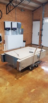
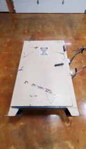
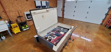
Behind my Inverts are two layers of 1/2'' cement board. It has been painted that's why it is hard to tell what it is. The bottom cabinet is 1/8'' steel with a 1'' air gap between it and the wall it is mounted to. I welded a 1x1 angle iron on the back to serve as a spacer. Inside the cabinet i used the 1/8 boards as a insulating barrier for the 48v circuits.
 
Behind my Inverts are two layers of 1/2'' cement board. It has been painted that's why it is hard to tell what it is. The bottom cabinet is 1/8'' steel with a 1'' air gap between it and the wall it is mounted to. I welded a 1x1 angle iron on the back to serve as a spacer. Inside the cabinet i used the 1/8 boards as a insulating barrier for the 48v circuits.
Got it! Looks amazing!
 
Got it! Looks amazing!
Thanks. You are definitely correct on pointing out fire hazard concerns. The picture on my profile is from a panel where a mouse chewed a 16 awg wire running to a shunt trip in a 1200 amp 480v service. The arcing started a chain reaction that lead to the hole burnt through the panel enclosure. If not for the air space behind the metal enclosure the building would have burnt down before the main breaker tripped. By the way the mouse did not survive the event.
 
Thinking I am going to trade out my 2 pole transfer switch for a 3pole based on this conversation.
https://diysolarforum.com/threads/n...ng-pip-3048lv-mk-48v-3kw-120v-inverter.35641/

This is my conclusion.

If the inverter disengages the line and neutral when in inverting mode it would be necessary for it to reestablish a neutral ground bond since it is the source of the power. This would allow the current to flow through the inverter back to the sub panel breaker to clear the fault. It would not need the bond in bypass since it is not the source. I have to admit that without a schematic from MPP it is hard to discern what is the proper method. I have had to go back and reread this whole book because of this ongoing discussion about these inverters. I should have been better versed in this but a rarely see this in my specific line of work.
  • 20220228_190502.jpg20220228_183136.jpg

 
This is the way I am wiring my system. It would never have the neutral and ECG bonded at more than one point at any given time. Since the two inverters communicating the way they are designed will both either be in bypass or inverting at the same time the system will only see one source.
LV6548 with 3pole transfer switch.png
After I have read all the input of others on this forum I think I should change my system wiring (shown above). By removing the ECG bonding screw from one of my Inverters N/G relays . After second and third guessing my own conclusions just looking for some input about doing this before moving forward.
 
Back
Top