boywonder
New Member
- Joined
- Jul 23, 2022
- Messages
- 19
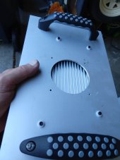
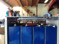
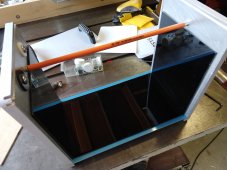
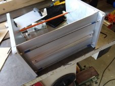
I'm replacing two aging 170ah AGMs in my camper van with this battery. The AGMs were Lucent/Alcatel server backup batteries and were about 7.5" wide, and the enclosure in the van just fit them.........so I'm limited to a width of 7.5" for the new pack. I'm fabricating it from aluminum because I'd like to have a non-combustible enclosure, I want stiff end plates for compression, and because I have a fair bit of scrap aluminum from other projects in the garage. 
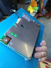
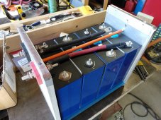
Cells are Eve LF280K 280ah cells each measuring 3.29V as shipped. They show some slight bulging, I'm assuming that's normal.
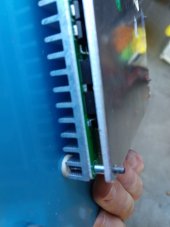
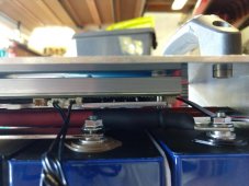
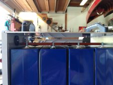
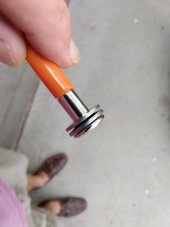
The end plates are 1/2" thick. I'm using female binder bolts/sex bolts typically used for furniture construction along with Belleville spring washers and 1/4-20 allthread for a compact enclosure design. The top, bottom and side plates are 1/8" aluminum and are free to slide around in 1/8" wide saw kerfs cut in the end plates with a non-ferrous saw blade....the end plates can easily expand/contract since the side and top/bottom plates are not fastened to either end plate.
Each all-thread rod and binder bolt has 4 stacked belleville spring washers that apply between 110 and 175 lbs on the pack providing between 6psi and 10psi and allows for about .048" or 1.2mm cell expansion total. If I need more travel I can add additional washers; each washer provides .012" of travel. I can also select stiffer bellevilles for additional load if needed. The bellevilles were purchased from McMaster as well as a bunch of other misc hardware and material.
The cells are separated from the case with 1/8" ABS sheet and some .050" thick stiff plastic between the cells (cut from old plastic three-ring-binders).
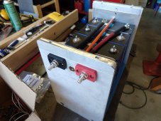
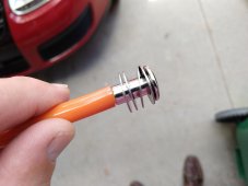
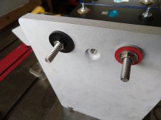
I've also machined up some delrin shoulder spacers for the external battery terminals.
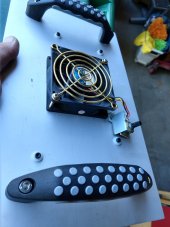
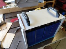
I'm waiting on a JBD 200A BMS; it hasn't arrived yet, but my plan is to mount it to the underside of the top cover for additional heat sinking.
A couple of questions:
Can I mount the JBD BMS directly to the aluminum enclosure? ...that's my present plan although I can mount it isolated if required.
I'm planning on using 5/16" brass screws for the battery terminals; I threw some 18-8 stainless screws in there as placeholders for now.....assuming brass is a better choice than stainless are far as conductivity goes. Are stainless screws/bolts for terminals a bad idea?
Not shown are the side covers......my plan is to have full covers so the case is completely enclosed with the BMS cooling augmented by using the top cover as additional sinking, but I can also easily provide venting around the top of the cells and the top cover. I like the idea of completely enclosed since the tight space it fits in is also lined with fuzzy trunk liner material. My loads are light except occasionally using a 700W microwave through a 1000W inverter that draws about 100 amps.
Cells are Eve LF280K 280ah cells each measuring 3.29V as shipped. They show some slight bulging, I'm assuming that's normal.
The end plates are 1/2" thick. I'm using female binder bolts/sex bolts typically used for furniture construction along with Belleville spring washers and 1/4-20 allthread for a compact enclosure design. The top, bottom and side plates are 1/8" aluminum and are free to slide around in 1/8" wide saw kerfs cut in the end plates with a non-ferrous saw blade....the end plates can easily expand/contract since the side and top/bottom plates are not fastened to either end plate.
Each all-thread rod and binder bolt has 4 stacked belleville spring washers that apply between 110 and 175 lbs on the pack providing between 6psi and 10psi and allows for about .048" or 1.2mm cell expansion total. If I need more travel I can add additional washers; each washer provides .012" of travel. I can also select stiffer bellevilles for additional load if needed. The bellevilles were purchased from McMaster as well as a bunch of other misc hardware and material.
The cells are separated from the case with 1/8" ABS sheet and some .050" thick stiff plastic between the cells (cut from old plastic three-ring-binders).
I've also machined up some delrin shoulder spacers for the external battery terminals.
I'm waiting on a JBD 200A BMS; it hasn't arrived yet, but my plan is to mount it to the underside of the top cover for additional heat sinking.
A couple of questions:
Can I mount the JBD BMS directly to the aluminum enclosure? ...that's my present plan although I can mount it isolated if required.
I'm planning on using 5/16" brass screws for the battery terminals; I threw some 18-8 stainless screws in there as placeholders for now.....assuming brass is a better choice than stainless are far as conductivity goes. Are stainless screws/bolts for terminals a bad idea?
Not shown are the side covers......my plan is to have full covers so the case is completely enclosed with the BMS cooling augmented by using the top cover as additional sinking, but I can also easily provide venting around the top of the cells and the top cover. I like the idea of completely enclosed since the tight space it fits in is also lined with fuzzy trunk liner material. My loads are light except occasionally using a 700W microwave through a 1000W inverter that draws about 100 amps.
Attachments
-
 Subassy 1.jpg1.1 MB · Views: 161
 -
 Subassy ABS.jpg1.1 MB · Views: 169
 -
 Subassy BMS space.jpg1.1 MB · Views: 165
 -
 Subassy 2.jpg1.1 MB · Views: 168
 -
 Belvilles 1.jpg964.7 KB · Views: 160
 -
 bellvilles 2.jpg57.9 KB · Views: 154
 -
 Subassy bottom.jpg1.1 MB · Views: 160
 -
 subassy front.jpg986.8 KB · Views: 157
 -
 countersunk hole.jpg1.1 MB · Views: 160
Last edited: