diy solar

diy solar

Finally found a LiFePO4 BMS with Low-temp Charging Protection

Hi everyone, I am the seller of the 120a BMS on Amazon.

I see this thread has been going on for quite a while... if there are any unsolved questions please bring me up to speed.

We can also talk about it on my reddit sub reddit.com/r/OverkillSolarBMS

I see that some of you are having trouble writing parameters with the android app, I found that it works better to change them one at a time on the “parameter view” page. Click on the value, it will pop up and say “Params setting”. Type in the new value and click confirm. It will write that single parameter to the BMS.

If at all possible use an iPhone. That app is much better developed.
 

Attachments

  • image.jpg
    image.jpg
    81.5 KB · Views: 30
Hi everyone, I am the seller of the 120a BMS on Amazon.

I see this thread has been going on for quite a while... if there are any unsolved questions please bring me up to speed.

We can also talk about it on my reddit sub reddit.com/r/OverkillSolarBMS

I see that some of you are having trouble writing parameters with the android app, I found that it works better to change them one at a time on the “parameter view” page. Click on the value, it will pop up and say “Paramus setting”. Type in the new value and click confirm. It will write that single parameter to the BMS.

If at all possible use an iPhone. That app is much better developed.
Welcome Steve, good to see pop in here..
 
And if you have agreed on a perfect set of parameters I would like to see it. I have some thoughts about balancing- it seems the stock setup is trying to do top balancing which is not very effective IIRC. What do you think?
 
A strange thing I noticed is that the android app shows more parameters than what you get to see on the iPhone. For example hardware over current and short circuit protection. Not that those should be changed but it’s interesting.

I want to work on a custom monitoring application, possibly arduino based. I don’t really have that kind of time tho...
Does the desktop version have some type of charting in it?
It would be nice if you could connect a laptop via Bluetooth...
I know in MacOS Catalina, there is some cross platform using iOS apps, but it's still in baby steps and I'm not that good at that stuff....
 
oh cool. Let me know if I can do anything to help. I will try out the library when I get a minute
If you have any input about these. See if you could get them to switch to three 8AWG B- & C- cables and double the length of them.
 
If you have any input about these. See if you could get them to switch to three 8AWG B- & C- cables and double the length of them.
I think that would be a change to the board because the holes are sized for 10ga

longer I could probably get for a few $...
 
FYI..... with 8 cells making a 12V battery, you can have a 2P4S or a 4S2P, but not a 4P4S..... For 4P you need 4 cells in parallel.....
This stuff can get confusing at first, but you'll get the hang of it.....

oh boy your not kiddin....
 
Hi everyone, I am the seller of the 120a BMS on Amazon.

I see this thread has been going on for quite a while... if there are any unsolved questions please bring me up to speed.

We can also talk about it on my reddit sub reddit.com/r/OverkillSolarBMS

I see that some of you are having trouble writing parameters with the android app, I found that it works better to change them one at a time on the “parameter view” page. Click on the value, it will pop up and say “Params setting”. Type in the new value and click confirm. It will write that single parameter to the BMS.

If at all possible use an iPhone. That app is much better developed.

Can you give the unsolved question linked below a go?

 
mndare on here swaped the 10AWG to 8AWG on his 120A version. Said the solder is real high temp and hard. Used a dremel to grid it down and get the old wires out and soldered in the new ones. See post 391 & 400 pg 20 in this thread.
https://diysolarforum.com/threads/f...ith-low-temp-charging-protection.2884/page-20

Confirmed! I went out to the garage and desoldered the leads from a BMS and sure enough the holes are big enough for 8ga wire.

My method for desoldering: I held the BMS in the bench vice and used the torch to heat a scrap of copper bar, with the flame aimed away from the BMS and held the bar on the solder. I singed the edges of the board a bit but I could have been more careful.
 
Ok I’m setting up Will’s 400 watt mobile system with alternator charging. https://www.mobile-solarpower.com/simplified-400-watt-fewer-wires-and-alternator-charging.html

I’m using 8 Fortune 100Ah LiFePo4 batteries in a 4P4S configuration. Here is Will’s Youtube video on this setup...

here are the specs for the batteries...View attachment 9683

I want to set the parameters in the BMS to conservative settings in order to make my batts last as long as possible. But I’m confused as to nomenclatur. For instance Will, in another posting, list’s absorption, float and invertercutoff as value‘s he would use, but this BMS has no such setting. https://diysolarforum.com/threads/r...e-for-diy-lifepo4-batteries-sticky-post.5101/

Also can anyone explain what a tripper value and a release value does? As far as I can tell there is no manual for this, on github or reddit. :mad:

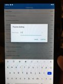
Here are the factor settings, can someone help me out here?

View attachment 9685
OK, so float and absorbtion voltage are settings on your charger. The BMS will disconnect the charger when the voltage rises to the Trigger value, either on one cell or the whole pack. The release value is when charging will be re-enabled.

example: using an unregulated charger, cell 1 rises to 3.650v (the high voltage cutoff, at this point the cell is over 100% charged) the BMS will disconnect/ block any more charging current. It will stay like this until the cell drops down to 3.500v, (from discharging)

You should be using a regulated charger that has a voltage limit (absorption voltage limit) set at like 14.2 to 14.4

With the lithium pack that I've been experimenting with, it tends to cut off for a single cell high voltage before the whole pack gets to 14.4v, but I am using the cheapest cells I could find. (possibly mismatched capacities)I have some good cells on the way.

Inverter cutoff is a setting on your inverter which is probably not adjustable, none of my inverters have that adjustment. The low voltage cutoff (pack or single cell) will cutoff the discharge current at whatever value you set it. Recommend 2.5v per cell / 10v pack.

Below 3.000v per cell there is like 1% of the capacity left so if you want to preserve cell life set the low voltage at 2.9v per cell / 11.6v pack

likewise, they are almost fully charged at 3.4v per cell.

A warning tho- having the BMS cutoff current can cause voltage spikes up the line that might damage your charger or load. Thats why they should be regulated so as to not reach the BMS cutoffs if possible.

The Github and reddit pages are a work in progress, I will probably polish this post a bit and put it in both places.

If I missed part of your question please let me know.
 
Confirmed! I went out to the garage and desoldered the leads from a BMS and sure enough the holes are big enough for 8ga wire.

My method for desoldering: I held the BMS in the bench vice and used the torch to heat a scrap of copper bar, with the flame aimed away from the BMS and held the bar on the solder. I singed the edges of the board a bit but I could have been more careful.
That's like, I'm curious what the difference beside the extra 2 wires, between the 100A and 120A versions. Not so curious I'm going to pull the heat shields off of them. Because I don't know if I could tell the differences if I did.... But it does make me go hmm. But if someone else did and made a video of it, I would watch it.

How hot do you think it was to melt the solder? My Chinese Ksger Digital Soldering Station, that uses T12 type tips, can go to 480℃, but I've read it is real hard on the tips and maybe the whole thing.
If I had to say how hot I would say very, lol. I think it’s more a question of thermal mass.

I have not had a 100a unit in my hands. If someone wants to I would be glad to compare and contrast. I’ll put it on my list to take some naked pictures. Of a BMS.
 
Back
Top