diy solar

diy solar

Small Boat BMS/LFP with backup

Looks good, personally I’d connect the limp home FLA connection with a manual switch , why bother with the cost of that relay when it might rarely be used. I’d also fit a manual bypass to the lithium relay , so the Li could be reconnected manually in extremis
I like these ideas are they both compliant with ABYC?:
1. Manual bypass switch to the lithium relay (and BMS) to reconnect the LFP to Loads and Chargers.
2. Replace 2nd Emergency relay connecting the FLA, with a manual switch.
3. Only one of these switches should be "On" at a time or the batteries will be connected.

The only disadvantage is that if sailing in the middle of the night with winds howling on a lee shore, with a tug towing a barge ahead, the BMS shuts off LFP and we are in the dark, no lights, nothing. Then we have to find the flashlights and perhaps have a headlamp, and get our heads around these two switches, or reset the BMS before we have nav lights or navigation.

What procedures when failure of LFP occurs?
 
Here is a Draft 8-25-2022 version showing a BMS controlled normally open relay to disconnect the LFP and a normally closed relay to connect the FLA in an "Emergency Limp Home Mode". This configuration would not leave the DC Panel dark after a failure which has some real benefits. I believe it meets the intent of ABYC. Does the second normally closed relay require a short timed delay? Any comments? How would be get the LFP back on line after an emergency BMS shutdown? What would the procedure be?
1. Check the condition of the battery through the GXtouch and Bluetooth
2. Check the condition of the BMS through the Bluetooth BMS app?
3. Check the condition of the Alternator and other charging devices through GXtouch?
5. If the LFP battery is overcharged or cells too high, how to discharge them? Turn on loads, stop chargers, and reset BMS and discharge LFP.
6. If the LFP battery is undercharged or cells too low, how to charge them? Turn off all loads and reset BMS and start engine and alternator charging?
5. Then depending on what is found, somehow reset the BMS to get the relay disconnect state changed?


Also revised the wiring for charging the FLA to be controlled from the DC Panel, since it is just using 15-18 amps and it allows me to turn off/on charging from the main panel, which also allows me to easily turn it off when in "Emergency Limp Home" mode.


View attachment 108432
Agree with @Goboatingnow, the limp home is unlikely to ever be used. Personally I just have a spare length of 10awg aboard for the situation if I really need it, and 10” of 2awg to bridge my alternator to my starter and hook it to the starter battery. That’s enough backup for my needs.

I would also stick to the REC diagrams and have your two contactors (whatever you’re using) wired to the battery. The diagram above indicates you’re cascading them which is not what you want. Also if you are using the victron smart battery protect220 for the charging side, remember that they’re unidirectional so you can’t have your load running through it backwards.

If there is an emergency shutdown, assume everything is off including your cerbo. You’ll need to check with the REC (doable if you buy their wifi module, screen, or computer cable) or just manually check the battery with a multimeter. Depending on what kind of shutdown it is, the REC will do different things. But you will likely never get there.

What I would do is set it up so that the LVC is a touch higher than the minimum voltage for the cells. You get there, the REC will drop your loads, but leave your solar running to recharge. I’m actually considering adding a second low side BatteryProtect to just power my cerbo, LTE router, and bilge pumps. Keep those going as long as possible, giving solar a chance to bring the voltage back up. The opto-isolator outputs of the rec should be able to drive a BatteryProtect no problem.

Either way, in 4 months of heavy use, I’ve never come close to a disconnect. The integration and comparatively large battery size has made sure that doesn’t happen. As long as you keep an eye in the system to ensure everything is communicating, you too should never wind up in that position.
 
svsagres wrote:
I would also stick to the REC diagrams and have your two contactors (whatever you’re using) wired to the battery. The diagram above indicates you’re cascading them which is not what you want.
I don't understand the first sentence, because I don't know what "...have the contactors (relays) wired to the battery" means.

I don't believe you read the notes at the bottom of the diagram. I do want them "cascaded" because the primary BMS coil relay (normally open) when the control power is off, fails to "open" and disconnects and isolates the entire LFP battery (both the charge bus and the load bus) as required by ABYC.

The second Emergency coil relay is normally closed, and it fails "closed" when power is off, thus connecting the DC Panel to the FLA battery and allows essential equipment to be powered.

Please see the diagram in Post #179

I've decided to use Blueseas Solenoid L-Series - 250A 12/24V #9012 $240 for the "B" primary relay coil. The other coil "C" could be a less expensive 50A coil, but I might just use a manual switch. This will use 0.13a x 24 hours = 3.12amps/day which currently is about 20%-25% of the daily solar output.

If there is an emergency shutdown, assume everything is off including your cerbo. You’ll need to check with the REC (doable if you buy their wifi module, screen, or computer cable) or just manually check the battery with a multimeter. Depending on what kind of shutdown it is, the REC will do different things. But you will likely never get there.

Is it possible to power the BMS and Wakespeed WS500 from the FLA instead of the LFP so that the monitoring functions do not shut down when the primary coil disconnects the LFP? Of course the sensor wires would be connected to the LFP. This would help us determine what the failure mode was.

Additionally, I need to show an "advanced alarm" circuit to meet ABYC.

Original Design Goal
Please keep in mind the original goal here was "Small boat BMS/LFP with backup" and in the first post I stated that the DC Loads should be powered by the FLA, because we should assume that the LFP are somewhat fragile and will fail sometime (in accord with John Harries). I have changed my attitude about that somewhat, by having the DC Loads powered by LFP and switched to FLA on failure.

...using the victron smart battery protect220 for the charging side, remember that they’re unidirectional so you can’t have your load running through it backwards.
Yes that is understood, but I don't believe I would be running my load through it backwards if I were using that device....
Come to think of it, I think I could use a Victron Battery Protect 65 for the "C" emergency connect coil.... I need to think about this a little further.

What I would do is set it up so that:
1. LVC is set a little higher than the minimum voltage for the cells.
2. When the BMS measures LVC it will drop your loads.
3. But leave your solar running to recharge.
I’m actually considering adding a second low side BatteryProtect to just power my cerbo, LTE router, and bilge pumps.
Keep those going as long as possible, giving solar a chance to bring the voltage back up.
The opto-isolator outputs of the rec should be able to drive a BatteryProtect no problem.
I see, you are discussing your configuration, because you are controlling essentially a charge bus and a load bus (dual bus configuration) you are trying to build in greater smarts for various conditions. Unfortunately that configuration does not meet ABYC requirements at present, unless you shut them both off on any failure.
As it is, I am unsure about my insurer's requirements, but I am certain they would want ABYC compliance. You may have a different situation.
 
Last edited:
svsagres wrote:

I don't understand the first sentence, because I don't know what "...have the contactors (relays) wired to the battery" means.

I don't believe you read the notes at the bottom of the diagram. I do want them "cascaded" because the primary BMS coil relay (normally open) when the control power is off, fails to "open" and disconnects and isolates the entire LFP battery (both the charge bus and the load bus) as required by ABYC.

The second Emergency coil relay is normally closed, and it fails "closed" when power is off, thus connecting the DC Panel to the FLA battery and allows essential equipment to be powered.

I've decided to use Blueseas Solenoid L-Series - 250A 12/24V #9012 $240 for the primary relay coil. The other coil could be a less expensive 50A coil, but I might just use a manual switch. This will use 0.13a x 24 hours = 3.12amps/day which currently is about 20%-25% of the daily solar output.

Is it possible to power the BMS and Wakespeed WS500 from the FLA instead of the LFP so that the monitoring functions do not shut down when the primary coil disconnects the LFP? Of course the sensor wires would be connected to the LFP. This would help us determine what the failure mode was.

Additionally, I need to show an "advanced alarm" circuit to meet ABYC.

Please keep in mind the original goal here was "Small boat BMS/LFP with backup" and in the first post I stated that the DC Loads should be powered by the FLA, because we should assume that the LFP are somewhat fragile and will fail sometime. I have changed my attitude about that somewhat, by having the DC Loads powered by LFP and switched to FLA on failure.
Both control relays provided by the REC present their NO ouputs on the harness (CH and DCH). If you cascade them, you can’t draw down your overcharged battery, since the DCH relay will be sitting open. but this is never going to happen because the REC is controlling all charging sources.

The BMS draws its power from the sense leads connected to the battery, so it will always be powered.

The WS500 actually has multiple voltage inputs. It draws its field power from the alternator, but needs is v+ to be connected to whatever it’s charging. This is so that its limp mode works properly and so it doesn’t overcharge the battery.

Remember, the AYBC recommendations are based on dumb, non-integrated systems. They’re also recommendations, not gospel. They’re not the equivalent of the NEC. If you can go beyond the recommendations and build a better system, then do it. You just need to be careful about it.
 
svsagres wrote:
Both control relays provided by the REC present their NO ouputs on the harness (CH and DCH). If you cascade them, you can’t draw down your overcharged battery, since the DCH relay will be sitting open. but this is never going to happen because the REC is controlling all charging sources.
Now I am understanding the CH and DCH outputs, which are both "Normally Open".
  • CH = Charge - intended for the Charge side.
  • DCH = Discharge - intended for the Loads and DC Panel side.
  • It is a standard "Dual Bus" setup.
Should I assume that REC has designed the operation of these Relays to
  • When LVC is reached drop the DCH relay to be Normally Open, and allow charging by solar or alternator to occur?
  • When HVC is reached drop the CH relay to be Normally Open, and allow continued discharge by the DC Panel?
  • The REC BME is being rational about the kinds of alarms that will occur and acting accordingly.
  • Also it appears to me that the BMS continues in operation and is powered in both conditions, so why should it shut down so that we cannot monitor battery conditions in the event of a failure?

As I understand the ABYC requirements, this does not comply! --Although it makes a good deal of sense to me.
Remember, the AYBC recommendations are based on dumb, non-integrated systems. They’re also recommendations, not gospel. They’re not the equivalent of the NEC. If you can go beyond the recommendations and build a better system, then do it. You just need to be careful about it.
I am going to have to think and read about this more.

The goal in my current diagram is to comply with ABYC and to provide FLA backup of the DC Panel. It uses a second "normally closed" relay to connect the FLA. This second relay is also powered by the BMS CH circuit.

Answered above:
The BMS draws its power from the sense leads connected to the battery, so it will always be powered.

Also re Wakespeed power:
The WS500 actually has multiple voltage inputs. It draws its field power from the alternator, but needs is v+ to be connected to whatever it’s charging. This is so that its limp mode works properly and so it doesn’t overcharge the battery.
 
Last edited:
svsagres wrote:

Now I am understanding the CH and DCH outputs, which are both "Normally Open".
  • CH = Charge - intended for the Charge side.
  • DCH = Discharge - intended for the Loads and DC Panel side.
  • It is a standard "Dual Bus" setup.
Should I assume that REC has designed the operation of these Relays to
  • When LVC is reached drop the DCH relay to be Normally Open, and allow charging by solar or alternator to occur?
  • When HVC is reached drop the CH relay to be Normally Open, and allow continued discharge by the DC Panel?
  • The REC BME is being rational about the kinds of alarms that will occur and acting accordingly.
  • Also it appears to me that the BMS continues in operation and is powered in both conditions, so why should it shut down so that we cannot monitor battery conditions in the event of a failure?
That’s correct. You can also set the opto-isolator outputs to act was what amount to the pre-warning outputs (though they’re voltage based rather than time based). The issue wrt the monitoring is that if it ever does release the DCH relay, that powers down your cerbo since it should be connected to the same load bus as everything else.

The other monitoring mechanisms optional with REC (wifi module, lcd, computer interface) will give you more information. You will need one of these to initially configure it to your system. I have the usb converter myself. That said, if I have a LVD, I can pretty quickly confirm that with the multimeter from my boat’s toolbox. But hopefully you have noticed beforehand :)

I have a little NodeRed bit going on my cerbo that will fire an email off to me if my SoC drops below 10% which, at idle, still gives me about 24 hours to deal with it. It will also automatically power on my multiplus if it’s connected to AC. I normally leave it off at the dock, but plugged in. That may change this winter once solar is no longer enough.

As I understand the ABYC requirements, this does not comply! --Although it makes a good deal of sense to me.

I am going to have to think and read about this more.

The goal in my current diagram is to comply with ABYC and to provide FLA backup of the DC Panel. It uses a second "normally closed" relay to connect the FLA. This second relay is also powered by the BMS CH circuit.

I still think this is a bit overly complicated and it’s a potential cause for failure. If you lose control over that relay that closes in the fla, bad things can happen depending on what exactly happens. A failure in the coil current, or the relay getting otherwise stuck means that your starter is hard connected to your lfp bus. I’m just as happy with my jumper wire.

If I lose the BMS while away at the dock, All I have to do is jump the B+ from the alternator to the starter solenoid, throw the disconnect on my lfp, and force my bluesea and BatteryProtect back on. Yeah, it will take me about 10-15 minutes to do this, but I can’t really foresee a time when that will be a safety problem to do so. And 18” of left over 2awg is cheap and cheerful.
 
Agree with @Goboatingnow, the limp home is unlikely to ever be used. Personally I just have a spare length of 10awg aboard for the situation if I really need it, and 10” of 2awg to bridge my alternator to my starter and hook it to the starter battery. That’s enough backup for my needs.
A simple switch or as you say , carry a jump lead , that’s what I use
I would also stick to the REC diagrams and have your two contactors (whatever you’re using) wired to the battery. The diagram above indicates you’re cascading them which is not what you want. Also if you are using the victron smart battery protect220 for the charging side, remember that they’re unidirectional so you can’t have your load running through it backwards.
He’s not using the smart battery protect in this latest ABYC compliant spec

If there is an emergency shutdown, assume everything is off including your cerbo. You’ll need to check with the REC (doable if you buy their wifi module, screen, or computer cable) or just manually check the battery with a multimeter. Depending on what kind of shutdown it is, the REC will do different things. But you will likely never get there.

What I would do is set it up so that the LVC is a touch higher than the minimum voltage for the cells. You get there, the REC will drop your loads, but leave your solar running to recharge. I’m actually considering adding a second low side BatteryProtect to just power my cerbo, LTE router, and bilge pumps. Keep those going as long as possible, giving solar a chance to bring the voltage back up. The opto-isolator outputs of the rec should be able to drive a BatteryProtect no problem.
ABYC and ISO , requires the safety disconnect to isolate the battery , you and others seem to have some mis understandings here. On a safety disconnect only the BMS must remain connected , both loads and charge sources must be disconnected.

Personally on a HVC or LVC I would never allow automatic recharge to occur until I had verified why the lvc event occurred , if you want to protect against over discharge , add a separate load disconnect device with a setpoint above LVC.
Either way, in 4 months of heavy use, I’ve never come close to a disconnect. The integration and comparatively large battery size has made sure that doesn’t happen. As long as you keep an eye in the system to ensure everything is communicating, you too should never wind up in that position.
AGREE , a safety trip, resulting is full battery disconnect , ie HVC , LVC , over-temp , over current should be treated as a non-normal safety event. Charge stop should occur below HVC and load disconnect should occur above LVC . A good BMS should have settable outputs to signal charge stop and load disconnect , separate to the safety disconnect trip points
 
Again to summarise what I regard as simple and best practice and ISO and ABYC compliant

1. A single fail safe contactor , activated by the BMS , disconnects the battery from both load and charge sources , the only remaining item left connected is the BMS.
2. By preference I would seperate load and charge busses , so option 1 needs a contactor on each bus , both contactors disconnect together on BMS safety trip
3, A BMS command should be available to reconnect the contactor or additionally a mechanical switch bypass , so that the battery can forcefully be reconnected.
4. In the case of dual contactors, overrides both BMS activated or manual switch overrides should be fitted to load and charge busses
5. Load disconnect should be a separate system , set to interrupt the feed to loads before LVC occurs , this allows charge sources to remain connected to the battery
6. HVC should never be used to stop charging normally. , chargers should stop themselves before HVC orvthe BMS separately should signal charge sources to stop
 
@Goboatingnow
So you'd like to have (2) relay coils Blueseas Solenoid L-Series 250a 12vdc 9012 $240 = $580 one for each bus (charge and discharge) That seems to be very expensive for the function, particularly if it is "never going to be used"! Actually it would be 3 relays.

I am serious about having the FLA backup function and don't want to be trying to sail and solve battery issues in the dark.
 
He’s not using the smart battery protect in this latest ABYC compliant spec
Yes, I noticed you scared him away from them after I wrote my lines above.
ABYC and ISO , requires the safety disconnect to isolate the battery , you and others seem to have some mis understandings here. On a safety disconnect only the BMS must remain connected , both loads and charge sources must be disconnected.
I will say it again: the documents as published by the ABYC are recommendations only. They do not have the force of law. In many cases, they are good recommendations and should be followed, other times they get it wrong. They are writing for the lowest common denominator. In this case, their requirement for a single disconnect does not take into account fully integrated systems, and thus, in my opinion, can be safely worked around.
Personally on a HVC or LVC I would never allow automatic recharge to occur until I had verified why the lvc event occurred , if you want to protect against over discharge , add a separate load disconnect device with a setpoint above LVC.
And that's what's integrated into the REC. You can set that low voltage disconnect at any point you want. I hate it set a reasonable point above the minimum called out in the datasheet for my cells. It will never, ever, get to a dangerous low on my system because the BMS will drop the load before it becomes dangerous and allow the charge sources to do their job. Even if the BMS takes a dump and doesn't drop the DCH line (highly unlikely given that it's on a NO relay), the built in intelligence in the BatteryProtect is configured to drop it about 0.05v lower than the BMS. In @rgleason's case, he doesn't have any loads on the charging side. In my case, I have a MultiPlus, but that won't run below the LVC because a) the multiplus has its own low voltage cutoff configured above the minimum pack voltage, b) it will be commanded off by the BMS as it gets close to the threshold and c) as a last ditch the relays will release.

AGREE , a safety trip, resulting is full battery disconnect , ie HVC , LVC , over-temp , over current should be treated as a non-normal safety event. Charge stop should occur below HVC and load disconnect should occur above LVC . A good BMS should have settable outputs to signal charge stop and load disconnect , separate to the safety disconnect trip points
Yes, all of that is configurable on the REC. The REC is in full control over the charging process, it commands the MPPTs, the battery charger, and the wakespeed to control the entire charging process. It sets both current and battery limits, and the thresholds are configurable.If it decides that it needs to do cell balancing, it will command a low current that is within its balancing capabilities. The whole point is to never ever get into a situation where the relays need to fire. It does all of this through CAN Bus and the CerboGX. On my system, I've configured all the devices to be more conservative in their charging than the BMS is, so if communications are lost or the Cerbo crashes, or the communication sotherwise goes south, it will fail into a conservative, safemode.

Without BMS control, the WS500 will limit Alternator output to 13.2V (roughly 50% on a LFP bank). My MPPT and MultiPlus are configured similarly. It's only when they're being commanded by the BMS that they will go through the whole charge profile.
 
@Goboatingnow
So you'd like to have (2) relay coils Blueseas Solenoid L-Series 250a 12vdc 9012 $240 = $580 one for each bus (charge and discharge) That seems to be very expensive for the function, particularly if it is "never going to be used"! Actually it would be 3 relays.

I am serious about having the FLA backup function and don't want to be trying to sail and solve battery issues in the dark.
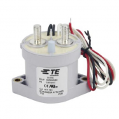
These are TE connectivity “ economiser “ relays in disguise , made in china , $50 , free shipping

The two relays are to allow the charge sources to be reconnected whilst leaving the loads disconnected

A conventional jump lead could be cheaply deployed to provide you with rare backup from the fla, if yiu get an unexpected Lvc , you’ll have to “ solve battery issues “ real quick anyway cause you’ll need to check your Li batteries anyway. , if you dont like jump leads , a simple manual switch is better, the NC relay doesn’t add much anyway
 

Attachments

  • AE528B14-3F22-4F14-9662-5642138F025B.png
    AE528B14-3F22-4F14-9662-5642138F025B.png
    280.3 KB · Views: 4
These are TE connectivity “ economiser “ relays in disguise , made in china , $50 , free shipping

The two relays are to allow the charge sources to be reconnected whilst leaving the loads disconnected

A conventional jump lead could be cheaply deployed to provide you with rare backup from the fla, if yiu get an unexpected Lvc , you’ll have to “ solve battery issues “ real quick anyway cause you’ll need to check your Li batteries anyway. , if you dont like jump leads , a simple manual switch is better
Yep, As I mentioned above, my strategy is to disconnect my LFP bank with a manual disconnect (I have a 600A BlueSea 3000 switch immediately after the Class T fuse to completely isolate the LFP bank from the rest of my boat. The jumper on my engine will then connect the + bus from the LFP side to the starter, thus letting me limp home.

I'll also need to disconnect the CAN to the BMS, if the BMS is still on (more likely I'll just turn off the BMS with its switch).
ABYC and ISO require BMS actioned autonomous disconnects with advance warning
 
ABYC and ISO require BMS actioned autonomous disconnects with advance warning
I was referring to bypassing a failed LFP system. The 600A disconnect is only there so I can safely service the rest of my system and/or implement the bypass.
 
Both control relays provided by the REC present their NO ouputs on the harness (CH and DCH). If you cascade them, you can’t draw down your overcharged battery, since the DCH relay will be sitting open. but this is never going to happen because the REC is controlling all charging sources.

The BMS draws its power from the sense leads connected to the battery, so it will always be powered.

The WS500 actually has multiple voltage inputs. It draws its field power from the alternator, but needs is v+ to be connected to whatever it’s charging. This is so that its limp mode works properly and so it doesn’t overcharge the battery.

Remember, the AYBC recommendations are based on dumb, non-integrated systems. They’re also recommendations, not gospel. They’re not the equivalent of the NEC. If you can go beyond the recommendations and build a better system, then do it. You just need to be careful about it.
That’s true for ABYC. of course if your in Europe you are subject to legally binding compliance
 
Good discussion above. Thanks. I will revise this Post #179 Draft Diagram again to show:
  1. A manual switch instead of the Emergency FLA normally closed relay coil.
  2. A single relay coil for both charge CH "B" and discharge DCH "C", normally open. Relay Coil TE $50 500A (smaller variants) type has the same “ economiser “ circuit which drops current to 130 mA like Bluesea https://a.aliexpress.com/_mPQ9QVK.
  3. Separate manual bypass switches for relay coil "B" and for "C" to be used once BMS LFP failure condition is determined. See post #198
  4. I understand now that this separation is useful after a BMS shutdown, after determining what went wrong:
    1. Goboatingnow : "two relays are to allow the charge sources to be reconnected whilst leaving the loads disconnected"
    2. For HVC charge failures (high cell voltage, overtemp) the Discharge bus would be reconnected to draw down the LFP.
    3. For LVC discharge failures (low cell voltage, overtemp) the Charge bus would be reconnected to recharge the LFP.
  5. Regarding ABYC and ISO standards re BMS failure and disconnection:
    1. I understand goboatingnow : "ABYC and ISO require BMS actioned autonomous disconnects with advance warning"
    2. and svsagres : "ABYC are recommendations, no force of law ..single disconnect does not take into account fully integrated systems, and thus, in my opinion, can be safely worked around." and later "AYBC recommendations are based on dumb, non-integrated systems. They’re also recommendations, not gospel. They’re not the equivalent of the NEC. If you can go beyond the recommendations and build a better system, then do it. You just need to be careful about it."
    3. goboatingnow: "That’s true for ABYC. of course if your in Europe you are subject to legally binding compliance"
    4. Don't know what I am going to do about this, but it probably depends on insurance involvement.
  6. Control, Monitoring, Sensing and Device power:
    1. REC BMS is powered from sense leads connected to the LFP battery, so it will always be powered as long as there is power.
    2. WS500 has multiple voltage inputs. Field power from the alternator, but v+ needs to be connected to whatever it’s charging so that emergency limp home mode works properly and it doesn’t overcharge the battery.
      1. So the v+ would need to be moved over to the FLA battery?
        1. No, not if it is connected to the alternator rather than the direct to the battery, with some small loss of charge rate that is insignificant for LFP (due to low resistance).
      2. svsagres wrote "Without BMS control, the WS500 will limit Alternator output to 13.2V (roughly 50% on a LFP bank). My MPPT and MultiPlus are configured similarly. It's only when they're being commanded by the BMS that they will go through the whole charge profile."
      3. If the Emergency FLA switch is ON, with the alternator charging the FLA will Alternator be limited to 13.2v?
      4. Should the red dashed emergency wire be changed from 6awg to 2awg due to alternator charging? (FLA is only 70ah).
        1. Changed in the lastest diagram
    3. MPPT Solar controllers, and Phoenix Charger normally powered from the LFP
      1. Upon REC BMS disconnect of the charge bus they will not be powered so their status will not be registered on the CerboGX and Bluetooth VictronConnect App will not work.
      2. When Emergency FLA switch is turned on, these devices will be charging the FLA and Bluetooth VictronConnect App will work.
    4. CerboGX power wires are not shown in the diagram.
      1. Power could be from the LFP discharge bus, so CerboGX + GXcolor50 will only work when that bus is connected to LFP.
      2. Could CerboGX be powered from the DC Panel so that it will be powered in Emergency FLA mode? Also the GXcolor50 is powered by the CerboGX USB. When the DC panel has power, the CerboGX will work.
    5. REC BMS Monitering/Control via RS485/PC or Remote Panel
      1. While sailing, with occurrence of a BMS LFP shutdown, I do not find use of PC and RS485 practical.
      2. While sailing, with occurrence of a BMS LFP shutdown, a Remote Panel would be useful but an expensive additional device.
      3. Can't the CerboGX + GXcolor50 be used?
  7. Actions needed upon BMS LFP shutdown:
    1. Use the boat's multimeter to determine the state of the battery. Voltage of each cell? Total voltage?
    2. Check temperatures with an infrared device.
    3. If the CerboGX is powered will we have access to BMS and WS500 information?
    4. If both "B" CH and "C" DCH are failed "open", Turn on the Emergency FLA switch to power up the DC Panel and CerboGX.
    5. If just "B" CH is failed "open" then the discharge bus is still on so the DC Panel and CerboGX is powered.
    6. If just "C" DCH is failed "open then there is no power to the DC Panel or CerboGX. Somehow force both "B" and "C" to fail open and only then Turn on the Emergency FLA switch to power up the DC Panel and CerboGX.
    7. With BMS separated "B" and "C" action, you at least have some idea of what the shutdown failure was!
@Goboatingnow Are you in US or Europe?
 
Last edited:
I’d agree with the comment that unexpected LVC or in fact HVC should never ever occur on a normal functioning system. Your battery monitoring system should be screaming at you if you are anywhere near LVC

Hence I think backup procedures to connect the FLA can be very haphazard , no more then most boats today with FLA have any redundancy arrangements either. In fact with Lithium better discharge range , you’re more likely in a FLA to have dead batteries then you are in a LI system.

Personally I’d save money on any redundancy bypass relays and invest it instead in load priority disconnects so that key equipment remains powered till the last minute.
 
The advantage in seperating the load and charge buses has been outlined in previous posts. The cost is an additional disconnect device slaved to the BMS

My own view is this is cheaper and practically effected by simply having a single disconnect and a manual charge bus override.( I would also include a load bus override as well by the way )

Hence after a safety disconnect , a manual intervention ( turn a switch ) is needed to reconnect the charge bus , whilst leaving the loads disconnected.

As I said , certainly on a boat , there is no way I want automatic recharge connection after a LVC safety trip. The battery needs to be physically examined before charge sources are reconnected. It would be a bad idea to reconnect charge sources to a damaged battery bank.
 
These are TE connectivity “ economiser “ relays in disguise , made in china , $50 , free shipping

The two relays are to allow the charge sources to be reconnected whilst leaving the loads disconnected

A conventional jump lead could be cheaply deployed to provide you with rare backup from the fla, if yiu get an unexpected Lvc , you’ll have to “ solve battery issues “ real quick anyway cause you’ll need to check your Li batteries anyway. , if you dont like jump leads , a simple manual switch is better, the NC relay doesn’t add much anyway
I wonder how much current these will use over 24hrs and how they compare to the more expensive Bluesea.
 
Back
Top