diy solar

diy solar

Your Charge Controller "Charges" the line between your Battery.

Status
Not open for further replies.
If, "Chare" (for practical purposes) flows instantaneously, and "Current" flows A LOT SLOWER, would it be possible to explain the Vdroop on a line?

Ugh. You have unwanted resistance in your cables, nothing more, nothing less.
 
Yes. It’s truely a bad charging regime and it will damage his batteries over time.
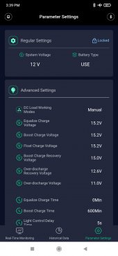
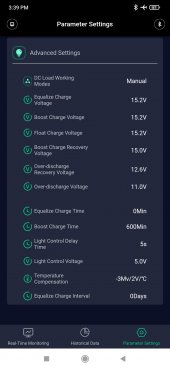
Hi, yea while I do have the allowable voltages cranked up to eliminate the charge controller from being a bottleneck in any way, as I said before, my batteries and never full when in use, and when I am not using the system, i charge up the battery and turn the system off. I appreciate your opinion on my charge parameters, and your opinion on they way I have my system configured. If you could give me real world datasheet from the manufacturer of my specific batteries, and show me where the manufacturer of my batteries states what is safe, and what is not... then, thank you very much for your opinion. I will push my system aggressively, and if my batteries "get damages" I will make sure to let you know.

On that note: Can you please help me by giving your system readings. Thank you for your help and assistance.


Attachments

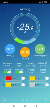
  • Screenshot_2022-08-27-15-39-12-559_com.paoding.heli_solar_app.jpg
    Screenshot_2022-08-27-15-39-12-559_com.paoding.heli_solar_app.jpg
    123.1 KB · Views: 0
  • Screenshot_2022-08-27-15-39-20-177_com.paoding.heli_solar_app.jpg
    Screenshot_2022-08-27-15-39-20-177_com.paoding.heli_solar_app.jpg
    125.8 KB · Views: 0
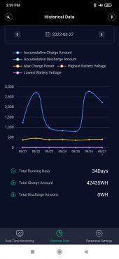
  • Screenshot_2022-08-27-15-39-36-784_com.paoding.heli_solar_app.jpg
    Screenshot_2022-08-27-15-39-36-784_com.paoding.heli_solar_app.jpg
    122.3 KB · Views: 0
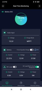
  • Screenshot_2022-08-27-15-39-57-758_com.paoding.heli_solar_app.jpg
    Screenshot_2022-08-27-15-39-57-758_com.paoding.heli_solar_app.jpg
    119.2 KB · Views: 0
  • Screenshot_2022-08-27-15-40-05-490_com.jiabaida.bms.jpg
    Screenshot_2022-08-27-15-40-05-490_com.jiabaida.bms.jpg
    225.9 KB · Views: 0
Brass is 7 times better conductor then steel , good busbars are copper or failing that brass often plated.
My steel analogy was probably a bad choice. However my understanding is brass is only 28 percent as conductive as copper. The important issue is the voltage drop on the wiring system. There could be several components causing that voltage drop.
Sure sense wires don’t cure drops but they do correctly compensate for it as you will always have some drop.
I only have one charger that has sense wires and the sense wires have a separate connection at the charger than the current carrying conductors. Unless his charge controller has separate sense wire inputs is there any other way that sense wires would be connected to provide that compensation? I am not disagreeing with your comment, I just don't know how that measurement would take place so that the drop could be compensated for? He does say he has the voltage cranked up to eliminate the charge controller from being the bottleneck. In a sense he has manually compensated for the voltage drop. The result is the BMS is disconnecting instead of allowing charging to terminate via the correct voltage setting.
 
Last edited:
Ugh. You have unwanted resistance in your cables, nothing more, nothing less.
Thank you for your information, it has been well received.

Can you please help us all by giving your readings as outlined in this post - thank you for all your assistance

 
Sure sense wires don’t cure drops but they do correctly compensate for it as you will always have some drop.
Sense wires only help compensate in the very small minority of Charge Controllers that can accommodate a sense wire input (or a remote sense like Victron). Most controllers don't know about a sense lead, and I would bet dollars to doughnuts the Chinese MPPT the OP has does not.
 
Does "Charge" flow faster than "Current"

If, "Chare" (for practical purposes) flows instantaneously, and "Current" flows A LOT SLOWER, would it be possible to explain the Vdroop on a line?

Back to the good'ol water analogy, volts-pressure, through partially opened water valve (resistance - or your CC cable circuit), current-flow trying to get that smaller orphice, raising the pressure (turning your charger up to high volts), pushes more current through the restriction.

As a result, the pressure measured before the valve, and after the valve, has a high delta... So the answer is, the 'Chare' is higher before the valve than after the valve, but the end voltage is higher overall, and the end current is higher overall, so the watts (GPM) is higher overall, thus masking the symptom of restriction in the middle.
 
Thank you for your information, it has been well received.

Can you please help us all by giving your readings as outlined in this post - thank you for all your assistance


BTW bro, did you ever get your cabinet in the kitchen torn apart so you can check everything out? Everyone maybe in suspense hehe... Did you ever get the 6 awg cable yet, maybe Amazon Prime One-Day or anything?

Did you see my post here yet on the answers to your questions from last night?
 
I hope so. He continues to think it is one wire and so far has not run the test on the entire wiring system as has been suggested many times.
Oh, Hi, I thought I made it clear to you and the others on this forum, many many many times that I am swapping out the wire with larger wire and double checking the connections - but just incase you missed it, I will state it again; I am upgrading the wire and triple checking the connections, and I plan on taking measurements with the wires connected directly from the Charge Controller to the Battery. I thought we hashed that out over a day ago, and I have repeatedly stated that a literal dozen times in the last 24 hours. Why then, now are you acting like you didn't hear or see me say that? When the wire is replaced and connected from the controller directly to the battery I will report my findings, as I've already stated. Thank you for your interest in this. EDIT: I am convinced. I am working on it. I am trying to catch up with everyone's posts from last night... I havdn't seen all your replies before I posted this so Never Mind... :)
 
BTW bro, did you ever get your cabinet in the kitchen torn apart so you can check everything out? Everyone maybe in suspense hehe... Did you ever get the 6 awg cable yet, maybe Amazon Prime One-Day or anything?

Did you see my post here yet on the answers to your questions from last night?
cable was "added to cart" but I got distracted by everything else on Amazing and i forgot to pull the trigger! lol I have a #6 cable that is connecting my 2 old lead acid batteries in parallel, I will use that, but its been too hot and I am busy with a thousand things, and if i get to it, it will have to be after the sun goes down because I'm getting low on juice.

I did see your post about your setup after I made that comment - I do appreciate the information - thank you.

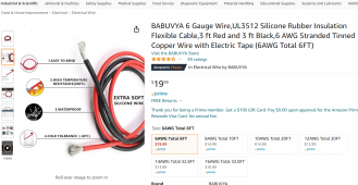
Edit: Picture of cable I intend to purchase
 

Attachments

  • 6 AWG Cable Amazon.PNG
    6 AWG Cable Amazon.PNG
    458.5 KB · Views: 8
Last edited:
Ugh. You have unwanted resistance in your cables, nothing more, nothing less.
Hi, well yes, totally agree that there is resistance, and I am addressing that - thank you

Please, please, please watch the video. At 17:24 they talk about the speed of "charge" vs the capacitance of the conductor. At this moment and several other times in the video, it is clearly highlighted that the "charge" on the conductor travels faster than the current.

I do not know the exact values do do the math and determine the equations, but if they are being omitted from theoretical calculations, they will create a discrepancy in the equations. I am no expert, but I did not see any "Maxwell equations" accompanying the equations that have been used earlier in this thread. Did you? What were they, what were the values? How were the calculated and included in the final equation, and do they line up with real world data from a large dataset? Where is this data, can you show it to me?

Thank you for your continued interest in this.


Edit: And can you please have a look at this thread and contribute if you have a qualifying system - thanks again

 
Please, please, please watch the video. At 17:24 they talk about the speed of "charge" vs the capacitance of the conductor.

I watched about 10 seconds and saw they were talking about AC not DC. Totally irrelevant to this thread.
 
Please, please, please watch the video. At 17:24 they talk about the speed of "charge" vs the capacitance of the conductor. At this moment and several other times in the video, it is clearly highlighted that the "charge" on the conductor travels faster than the current.
Do yourself a favor. For the purposes of everything we do here, all current - charging and discharging - is passing at the speed of light. Essentially instantaneously. There is absolutely no value in discussing the "speed of current" vs the "speed of charge". Most of what you need for what is discussed here is just Ohm's Law. Veritasium's videos (including the one you found) are entertaining for those of us interested in science (I've watched many of his videos) but of absolutely no use when designing a solar power system. Also, @Texas-Mark is right that the particular video you pointed to is specific to Alternating Current. Not useful on the DC side of your inverter. Just look up Ohm's Law, and study it.
 
I told you I'd get numbers for you. It wasn't quite peak sun and I had some loads running, but here's my numbers.
Charging at roughly 55.2 amps.

Charger measurement/display: 53.5 volts
Actual measurement at charger terminals: 53.03 volts
BMS measurement/display: 52.93 volts
Actual measurement at batt terminals (after BMS/shunt) 52.86 volts

You can see the inaccuracy in my charger's voltage measurement, hence the insistence to ignore this voltage reading until you know how it compares at different current.
In total, my system has 0.17 volts of loss in: 2 breakers, 1 shunt, 2 bus bars, and 25 feet of 0000 cable.
Hey, thank you for that information. That is very clear. Can I ask you what was the batteries state of charge?

I don't want to re-repeat my questions, or requests, but I did post this Thread, and if you could make sure the battery is sufficiently depleted & take the measurements around 12/1pm - And try to get App Screenshots and even a Snap of the Multimeter. This will go a long way in establishing real world data - thank you again

 
Hey, thank you for that information. That is very clear. Can I ask you what was the batteries state of charge?
80% ish
But it doesn't matter.

I don't want to re-repeat my questions, or requests, but I did post this Thread, and if you could make sure the battery is sufficiently depleted & take the measurements around 12/1pm - And try to get App Screenshots and even a Snap of the Multimeter. This will go a long way in establishing real world data - thank you again
So, you clearly don't believe what everyone is telling you if you're posting a thread to compare to others.

Stop posting and got take some dang voltage drop measurements.
Find and correct the problem.
 
Do yourself a favor. For the purposes of everything we do here, all current - charging and discharging - is passing at the speed of light. Essentially instantaneously. There is absolutely no value in discussing the "speed of current" vs the "speed of charge". Most of what you need for what is discussed here is just Ohm's Law. Veritasium's videos (including the one you found) are entertaining for those of us interested in science (I've watched many of his videos) but of absolutely no use when designing a solar power system. Also, @Texas-Mark is right that the particular video you pointed to is specific to Alternating Current. Not useful on the DC side of your inverter. Just look up Ohm's Law, and study it.
Point of Fact: Maxwell's equations are relevant to both AC and DC

Thank you for your interest in this. Do you have any data set that states the Charge Speed, vs. the Current Speed? Do you have any equations built into the Ohm's Law in regards to the the Quantum Mechanical Principles in the Maxwell Equations.

Do you have any real world data set to backup your claim. What is your system configurations, and what are the readings at your terminals - can you tell us your system specs, usage scenarios, battery state of charge, etc.

I really appreciate your interest in this, and since you and so many others are so very keen on chiming in, can you please take 5 or 10 minutes and take the readings off of your system and include the App screenshots and pictures of your multimeter on your system - it is greatly appreciated. Thanks you again

 
Now i am starting to think we are just being trolled.
Point of Fact: Maxwell's equations are relevant to both AC and DC

Thank you for your interest in this. Do you have any data set that states the Charge Speed, vs. the Current Speed? Do you have any equations built into the Ohm's Law in regards to the the Quantum Mechanical Principles in the Maxwell Equations.

Now I think we are just being trolled. I for one have pretty much had enough of this foolishness.
 
80% ish
But it doesn't matter.
Dear Sir, I beg to differ. The Battery State Of Charge IS very important, because the lower the State Of Charge, the more the battery will Absorb.

Again, thank you for your readings. You, and maybe one other person, are the only people who have actually attempted to give readings, but I didn't get a clear data spec from either of you to work with.

I took pictures and screenshots and explained the exact state and configuration of my system, and all in all it only took me 20 minutes, including the time it took me to post the information. But anyway, thank you for your recommendations and continued interest in this.

Oh, also, if you know anyone with a qualifying system, could you ask them to take & report their measurements - thanks again, you have been very helpful

EDIT: Have them fill this out:
 
I still would suggest as other people had already suggested, check Vdrops between two ends the wires, on the circuit breaker/fuse, bussbar, etc, then if you change the wires then you will have a ref. to compared to, then you can also try tighten the connection and see if there are changes in the Vdrops, it is so easy to do to measure the Vdrops between 2 points.,
BTW, do you have breaker/fuse between SCC and the batteries?
I do not have a fuse from the SCC to the Battery/Busbar. The SCC has fuse built in.

This evening, very shortly, I will be swapping out the 8AGW for a 2'6AWG, and tomorrow I will take readings from morning to night.

What is your system configuration, and what are the readings at the terminals of your battery and scc? what is your daily usage scenario, and your battery state of charge?

Can you please look at this thread, and if you, or someone you know has a qualifying system, can you take the readings, it would go a long way to building a real world datasheet - thanks again

 
Status
Not open for further replies.
Back
Top