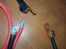
No Sht! I just realized that the wire is copper coated crap! Look at the very end of the strands... Do you see the aluminum discoloration!There’s 30 A going through this stuff , where I’m from that’s called an electric heater !


You are using an out of date browser. It may not display this or other websites correctly.
You should upgrade or use an alternative browser.
You should upgrade or use an alternative browser.
Your Charge Controller "Charges" the line between your Battery.
- Thread starter Michael77
- Start date
- Status
- Not open for further replies.
I was about to comment just the same.No Sht! I just realized that the wire is copper coated crap! Look at the very end of the strands... Do you see the aluminum discoloration!
This thread has been filled with your weird ideas and you obviously don't have even basic understanding of electrical theory so I'll put this bluntly:
Your cable terminal crimps look like SHIT. Get proper tools for the job and learn to make crimps that don't look like they were done by 5-year old.
Goboatingnow
Solar Enthusiast
- Joined
- Jul 3, 2022
- Messages
- 1,325
No Sht! I just realized that the wire is copper coated crap! Look at the very end of the strands... Do you see the aluminum discoloration!
Your mppt scc issues sorted
Gather all that wiring and connectors , walk to a garbage unit , deposit all inside with attitude
Buy appropriate tinned stranded quality conductors and proper crimp terminals ( not those cheap car types ) re install , watch your SCC voltage converge on the battery terminal voltage
Sit back and thank the experts here. Re-assess your theoretical knowledge and enjoy a contended Henri Winterman moment.

I've just gone through 20+ reports on comments in this thread. I'm sorry @Michael77: misunderstanding and comments trying to help you are not personal attacks or spreading false information.
As an electrical engineer, I will say one thing: listen to the other people in this thread that have experience. Don't dismiss what they say "spreading false information" because you think you know better. I've kept out of the discussion myself because I didn't want to get dragged into another long, tedious thread.
Keep it civil, stop reporting comments that are perfectly fine, and I'll leave this thread up. If the same pattern continues, I will close the thread.
am just all around tired, angry and bitter, but that did make me laugh - they do look like shit! I built that cable a couple years ago when I first started, its so stupid you have to spend 30/50/100/200/300 dollars on tools you will only use once or twice a decade. I really really would love to have one of those phneumatic crimpers, etc etc etc - but I am on a tight budgetI was about to comment just the same.
This thread has been filled with your weird ideas and you obviously don't have even basic understanding of electrical theory so I'll put this bluntly:
Your cable terminal crimps look like SHIT. Get proper tools for the job and learn to make crimps that don't look like they were done by 5-year old.
I will not use the "reusable" connectors, but what do you think about them, they are heavy copper, just the inner diameter is only 1/4" and they are perfect for my small 12 fuse panel, but I don't think they are big enough for the SCC Cable...
Attachments
Goboatingnow
Solar Enthusiast
- Joined
- Jul 3, 2022
- Messages
- 1,325
At least now you’re left the “ cult of Michael77” , had your mind cleared of that brainwashing and look forward to a life consistent with ohms law. !am just all around tired, angry and bitter,
I’d say the community had done well in its intervention to save you from that cult.
I understand and I got it. I do have to say, some of the comments were completely disrespectful, repetitive harassment, and personal attacks. I have a thick skin, but look closely and you will see a pattern of me repeating my statements and assertions, not because I was trying to prove, over and over my point, per say, but because others kept telling me the same thing over and over againI've just gone through 20+ reports on comments in this thread. I'm sorry @Michael77: misunderstanding and comments trying to help you are not personal attacks or spreading false information.
As an electrical engineer, I will say one thing: listen to the other people in this thread that have experience. Don't dismiss what they say "spreading false information" because you think you know better. I've kept out of the discussion myself because I didn't want to get dragged into another long, tedious thread.
Keep it civil, stop reporting comments that are perfectly fine, and I'll leave this thread up. If the same pattern continues, I will close the thread.
And, I will say, if ANYONE tells me the BMS is not designed to stop the charge cycle. I want to laugh in their face so hard it's ridiculously hilarious that people think LFP Lead Acid Drop In Replacement Batteries are not supposed to be charged up until their BMS turns off the charge cycle - that, coming from "Admins" and "Staff" and "Experts" is so completely and totally laughable it's actually frightening. I hold my tongue and politely reiterate and explain why I believe that is not the case. Which if you read the thread, I explain very very clearly and not one single person has any justification for saying otherwise. But they keep repeating it over and over...
Just somethings to consider - I got what you are saying though, and I will swap out the wire and run the test tomorrow.
I have to ask. What happens IF, lets just say "IF" the Vdroop is not gone, or only slightly better, what then?
Do you have any problem taking measurements on your own system and sharing them - is there any harm in sharing system specs, settings, configurations etc like I ask in the thread below. At the end of the day, a real world database can only be helpful, do you agree?

HELP NEEDED: If you have a ~1KW or less, Solar System w/ Lithium Iron Phosphate Batteries
HEADER: FOR DATA GATHERING PURPOSES, PLEASE LIMIT THE COMMENTS IF YOU DO NOT HAVE THE REQUESTED INFORMATION – THIS WILL HELP THE PROCESS OF GATHERING REAL WORLD DATA – THANK YOU If you feel like commenting on this post, please at the top of your comment state: I Do Not Have Qualifying Data –...
 diysolarforum.com
I'm not in a Cult, I'm in a SUPERCULT of 1, And don't forget, tomorrow I will still run the test as i laid out above. We will see. There may still be some/a lot higher vdroop in the line than people expect. And I still want everyone else's real world measurements - it can't hurt to have real world data.At least now you’re left the “ cult of Michael77” , had your mind cleared of that brainwashing and look forward to a life consistent with ohms law. !
I’d say the community had done well in its intervention to save you from that cult.
And, I will say, if ANYONE tells me the BMS is not designed to stop the charge cycle. I want to laugh in their face so hard it's ridiculously hilarious that people think LFP Lead Acid Drop In Replacement Batteries are not supposed to be charged up until their BMS turns off the charge cycle - that, coming from "Admins" and "Staff" and "Experts" is so completely and totally laughable it's actually frightening.
The BMS is not designed to stop the charge cycle. The BMS is a safety device, there to protect the battery if something goes wrong at cell level. The charge controller should stop the charge cycle.
Do you have any problem taking measurements on your own system and sharing them - is there any harm in sharing system specs, settings, configurations etc like I ask in the thread below. At the end of the day, a real world database can only be helpful, do you agree?
I've done that many times. You're facing the same issue that people balancing their cells have. They put on a power supply on their cells, notice the power supply doesn't give the full 10A it can deliver, and increase the voltage - instead of replacing the alligator clamps and putting better wire. I wrote this because it kept coming back:
DIY Battery Handbook
With the increasing amount of users on the DIY Solar Forum and more people exploring the options to build their own battery packs we've seen common mistakes and dangerous situations occur more frequently - sometimes with disastrous outcomes. While many of the issues we come across have been...
diysolarforum.com
What do you expect after your own comments like "If you still want to argue, I will immediately know that you have no clue how electricity works and I will probably go out of my way to report you." ?I understand and I got it. I do have to say, some of the comments were completely disrespectful, repetitive harassment, and personal attacks. I have a thick skin, but look closely and you will see a pattern of me repeating my statements and assertions, not because I was trying to prove, over and over my point, per say, but because others kept telling me the same thing over and over again
You got quite ass-whooping here(well-earned in my opinion)
 but at least in the end you seem to be capable admit your own errors and dig deeper and learn more about the subject.
-----
You don't need to spend fortune on crimpers or terminals, just do some smart shopping. And that is not necessarily same that Will is touting on youtube.
Where are you getting that from? Have you actually watched any of Wills videos? Have you watched any of Hobos Videos? Or Lithium Solar?The BMS is not designed to stop the charge cycle. The BMS is a safety device, there to protect the battery if something goes wrong at cell level. The charge controller should stop the charge cycle.
I really want to know where you are getting that from. The Professionals, Including Will, Hobo, Lithium Solar, DPoz, all whom test and evaluate hardware for a living - THEY ALL USE THE BMS TO STOP THE CHARGE CYCLE!
Look, I realize you are admin and you have a heavy load on your plate, I can't even imagine; but please, Look at this argument I have made, and answer the questions to the points I bring up. Your information may be outdated...
"
It is too early to make any decisions on my final MPPT Parameter settings until I make sure ALL cables are large enough, and triple check all connections, etc. But I already know that the default LFP setting for this MPPT Controller doesn't cut off the voltage when the battery is full, that is handled by the BMS on the Battery. I ran the system in the default settings for the first week and I charged up the system to full, twice. Both times; the BMS turned off the charging cycle, it literally flipped the charge toggle off, and I could not manually turn it back on until the "Charge Voltage Disconnect Release Voltage" was hit. Then it would toggle charging back on. Or allow me to manually toggle it.
I had a non-programmable Renogy Wanderer 30 Amp LFP Version Charge Controller for 2 years and the only way to stop charging was when the batteries BMS would kick in and stop the charging cycle. That was how it was designed to work and it worked great for 2 year.
This new MPPT charge controller has a "LI" setting that is explicitly for LFP and it too works just like the Renogy Wanderer, the only way the charge cycle stops is when the Batteries BMS kicks in.
This new MPPT also has a "USE" setting for User Programable Parameters, but again, there IS not High Voltage Disconnect setting and the only way the charge cycle is stopped is if the batteries BMS stops the charging into the battery.
I do realize a lot of people in the forum are saying the same thing as you, that I shouldn't use the battery BMS to stop charging, but that is literally how its designed to work. I literally have no other way to stop the charge cycle unless I would sit there and manually do it, and you know that is practically impossible.
And then there is the Wall Chargers that I have, designed for LFP, they do not stop sending current and the only way I know my battery is fully charged is when the BMS says 100% and stops the charging.
And, on top of that, all the advertisements around new LFP batteries talk about "Lead Acid Drop In Replacement" meaning these Batteries are designed to work with a wide range of hardware designed for 12v Lead Acid Equipment. Including Lead Acid Chargers, Inverters, etc - these devices cover a wide rang of usage scenarios and parameters, and LFP batteries with internal BMSs are designed with this in mind, meaning the BMS was designed to be used to disconnect the current once the battery is charged. That, and many other conveniences of modern electronics like cell balancing functions, over-current, over-charge, reverse polarity, over-discharge, etc - all these functions are built in and guaranteed by the battery manufacturers.
If they fail, its the manufacturer who will have to cover the replacement costs, at the least. (And I don't want to get into the minutia of fly by night cheap sellers, etc, that is not the point... though it is a consideration)"
Also, I know you have taken measurements of your system before, but can you do it again? it is literally like 10 minutes and everyone wants to make comments and ague, but when I ask for some simple real world data that was virtually demanded of me, no on want to give their data - I do start to wonder... Why are people saying one thing, but not taking the few moments that would be required to say see: my system is operating just like I said... hmmm? BMS can't stop the charge cycle; listen to what I say, I won't give you my data...? ... ... ??? straing... very straing...
Well, I will run the test tomorrow with the upgraded cable directly into the busbars/battery and we will see. I still don't see your specs like I have asked people to help with. Do you think a real world data set would confirm what people are saying, and if so, do you expect people to give their measurements so we have real world data to go off?What do you expect after your own comments like "If you still want to argue, I will immediately know that you have no clue how electricity works and I will probably go out of my way to report you." ?
You got quite ass-whooping here(well-earned in my opinion)
-----
You don't need to spend fortune on crimpers or terminals, just do some smart shopping. And that is not necessarily same that Will is touting on youtube.
I showed you mine, now you show me yours (ahahahaha that doesn't really sound right... lol)
HELP NEEDED: If you have a ~1KW or less, Solar System w/ Lithium Iron Phosphate Batteries
HEADER: FOR DATA GATHERING PURPOSES, PLEASE LIMIT THE COMMENTS IF YOU DO NOT HAVE THE REQUESTED INFORMATION – THIS WILL HELP THE PROCESS OF GATHERING REAL WORLD DATA – THANK YOU If you feel like commenting on this post, please at the top of your comment state: I Do Not Have Qualifying Data –...
diysolarforum.com
Samsonite801
Solar Wizard
- Joined
- Oct 15, 2020
- Messages
- 2,994
And, I will say, if ANYONE tells me the BMS is not designed to stop the charge cycle. I want to laugh in their face so hard it's ridiculously hilarious that people think LFP Lead Acid Drop In Replacement Batteries are not supposed to be charged up until their BMS turns off the charge cycle - that, coming from "Admins" and "Staff" and "Experts" is so completely and totally laughable it's actually frightening. I hold my tongue and politely reiterate and explain why I believe that is not the case. Which if you read the thread, I explain very very clearly and not one single person has any justification for saying otherwise. But they keep repeating it over and over...
We do have free agency to believe anything we want to, the BMS can be whatever to you as you feel so fit. The laws of this physical world will keep going and not lose any sleep over it.
I personally like the idea though, of a BMS being a second method / layer of control / safety, so in effect, charger (pack-level) control first and then BMS (pack-level & cell-level) control can give two layers of redundancy in maintaining good overall battery health to help ensure you the best service life for your money.
That's why I prefer to make use of both layers, since they are there already for me to use. But that's just my own thinking...
Keep in mind there are a handful of people in the marine community who prefer and feel it is acceptable to run LFP without BMS at all (let the charger handle the whole thing, no cell-level safety, no balancing, only pack level management), which is fine if that's what they want to do.
Check this out as well:
Battery management system - Wikipedia
You can interpret that information any way as you prefer, and use the BMS any way you like. That's the beauty of free agency.
Cheers bro..
Last edited:
Thank you for your cordial reply and perspective. I respect that. I too would love to have double protection, especially with a system that had data ports so I could get the absolute most energy into my system and still have the layers of safety you mentioned.We do have free agency to believe anything we want to, the BMS can be whatever to you as you feel so fit. The laws of this physical world will keep going and not lose any sleep over it.
I personally like the idea though, of a BMS being a second method / layer of control / safety, so in effect, charger (pack-level) control first and then BMS (pack-level & cell-level) control can give two layers of redundancy in maintaining good overall battery health to help ensure you the best service life for your money.
That's why I prefer to make use of both layers, since they are there already for me to use. But that's just my own thinking...
Keep in mind there are a handful of people in the marine community who prefer and feel it is acceptable to run LFP without BMS at all (let the charger handle the whole thing, no cell-level safety, no balancing, only pack level management), which is fine if that's what they want to do.
Check this out as well:
Battery management system - Wikipedia
en.wikipedia.org
You can interpret that information any way as you prefer, and use the BMS any way you like. That's the beauty of free agency.
Cheers bro..
I do have a message out to the Manufacturer of my BMS. I hope to share their reply soon.
EDIT: Here is an example of a "LFP Lead Acid Drop In Replacement Battery" This guy absolutely hammered it, and it operated well above rated specs. Not to beat a dead hours, I just wanted to share...
Attachments
Last edited:
Hi, here is an example of a "LFP Lead Acid Drop In Replacement Battery" Fully Guaranteed by the Manufacturer for 5 years, and I quote:The BMS is not designed to stop the charge cycle. The BMS is a safety device, there to protect the battery if something goes wrong at cell level. The charge controller should stop the charge cycle.
"You do not need a special lithium charger or lithium solar controller" Guaranteed for 5 years by manufacturer!
I recommend you watch the whole video and re-evaluate your presumably internal group policy on telling people, or implying that "you can't use the BMS to stop the charge cycle." or that "The BMS is not designed to stop the charge cycle. The BMS is a safety device, there to protect the battery if something goes wrong at cell level. The charge controller should stop the charge cycle."
In this regard, you are incorrect, and so is everyone else on this forum who keeps repeating the same thing. This is insane, a DIY Solar Forum created by a guy who sells new modern LFP Drop Ins Batteries, his own Admins, Staff & "Experts" are saying this? Does he know you are saying this? You should ask him.
Ampster
Renewable Energy Hobbyist
Default setting? Let's talk numbers. The voltage is set for 15.2 volts which is 3.8 volts per cell. That cannot be a default setting. Earlier you sad you thought 3.55 per cell was a good number so try 14.2 for Boost voltage. If your BMS is still terminating charge then look at the history in your BMS and see if a cell has gone over 3.65 volts. If that is the case your cells are out of balance.But I already know that the default LFP setting for this MPPT Controller doesn't cut off the voltage when the battery is full, that is handled by the BMS on the Battery.
Ampster
Renewable Energy Hobbyist
I watched the video and the guy clearly says you can use a charger that is set for 14.4 to to 14.6 volts. That is the typical Lead Acid charging voltage not the 15.2 volts that your charge controller is set for.I recommend you watch the whole video and re-evaluate your presumably internal group policy on telling people, or implying that "you can't use the BMS to stop the charge cycle." or that "The BMS is not designed to stop the charge cycle.
You said earlier that you thought 3.55 was a good setting so try 14.2 and see what happens.
Last edited:
Ampster
Renewable Energy Hobbyist
It is clear he also needed better crimps and quality wire and he does not have a charge controller with sense leads.That’s he needs cables the size of pipes
Texas-Mark
Solar Addict
- Joined
- Aug 4, 2021
- Messages
- 1,300
Okay. How do you account for the Vdroop from 19v to 15v from my panels to the charge controller?
Well, this is a new one. I am assuming you are talking about taking a reading while the panels are disconnected and then connected. If so you once again don't know have even a basic understanding of electricity, or how solar panels work.
Regarding the lack of proper fusing. You never answered my question about what happens if your positive wire comes out of the charge controller for whatever reason, and lands on a negative terminal. Going to rely on your BMS to save the day too?
You still refuse to accept that the BMS is not designed to be used solely as a high voltage cutoff, and that it is there as a failsafe backup to protect the cells, no matter how many people tell you. Videos that may show someone using it intentionally as a cutoff most likely are just testing that it works, or simplifying their video for whatever reason. These "drop in" batteries 99% of the time will fall into FLA voltage ranges.
I still can not believe that you keep telling everyone here that are wrong about pretty much every aspect of this thread.
Never in any of my videos have I used BMS HVD to stop charging from a PV controller. I have always stated that BMS is used as last resort. Charge controller absorption voltage should always be lower than BMS HVD threshold. I only trigger HVD for capacity testing. I have mentioned this multiple times in the videos.Where are you getting that from? Have you actually watched any of Wills videos? Have you watched any of Hobos Videos? Or Lithium Solar?
I really want to know where you are getting that from. The Professionals, Including Will, Hobo, Lithium Solar, DPoz, all whom test and evaluate hardware for a living - THEY ALL USE THE BMS TO STOP THE CHARGE CYCLE!
Look, I realize you are admin and you have a heavy load on your plate, I can't even imagine; but please, Look at this argument I have made, and answer the questions to the points I bring up. Your information may be outdated...
"
It is too early to make any decisions on my final MPPT Parameter settings until I make sure ALL cables are large enough, and triple check all connections, etc. But I already know that the default LFP setting for this MPPT Controller doesn't cut off the voltage when the battery is full, that is handled by the BMS on the Battery. I ran the system in the default settings for the first week and I charged up the system to full, twice. Both times; the BMS turned off the charging cycle, it literally flipped the charge toggle off, and I could not manually turn it back on until the "Charge Voltage Disconnect Release Voltage" was hit. Then it would toggle charging back on. Or allow me to manually toggle it.
I had a non-programmable Renogy Wanderer 30 Amp LFP Version Charge Controller for 2 years and the only way to stop charging was when the batteries BMS would kick in and stop the charging cycle. That was how it was designed to work and it worked great for 2 year.
This new MPPT charge controller has a "LI" setting that is explicitly for LFP and it too works just like the Renogy Wanderer, the only way the charge cycle stops is when the Batteries BMS kicks in.
This new MPPT also has a "USE" setting for User Programable Parameters, but again, there IS not High Voltage Disconnect setting and the only way the charge cycle is stopped is if the batteries BMS stops the charging into the battery.
I do realize a lot of people in the forum are saying the same thing as you, that I shouldn't use the battery BMS to stop charging, but that is literally how its designed to work. I literally have no other way to stop the charge cycle unless I would sit there and manually do it, and you know that is practically impossible.
And then there is the Wall Chargers that I have, designed for LFP, they do not stop sending current and the only way I know my battery is fully charged is when the BMS says 100% and stops the charging.
And, on top of that, all the advertisements around new LFP batteries talk about "Lead Acid Drop In Replacement" meaning these Batteries are designed to work with a wide range of hardware designed for 12v Lead Acid Equipment. Including Lead Acid Chargers, Inverters, etc - these devices cover a wide rang of usage scenarios and parameters, and LFP batteries with internal BMSs are designed with this in mind, meaning the BMS was designed to be used to disconnect the current once the battery is charged. That, and many other conveniences of modern electronics like cell balancing functions, over-current, over-charge, reverse polarity, over-discharge, etc - all these functions are built in and guaranteed by the battery manufacturers.
If they fail, its the manufacturer who will have to cover the replacement costs, at the least. (And I don't want to get into the minutia of fly by night cheap sellers, etc, that is not the point... though it is a consideration)"
Also, I know you have taken measurements of your system before, but can you do it again? it is literally like 10 minutes and everyone wants to make comments and ague, but when I ask for some simple real world data that was virtually demanded of me, no on want to give their data - I do start to wonder... Why are people saying one thing, but not taking the few moments that would be required to say see: my system is operating just like I said... hmmm? BMS can't stop the charge cycle; listen to what I say, I won't give you my data...? ... ... ??? straing... very straing...
I really think you need to pick up a basic electronics book from the library and study it for a few weeks. Or watch some beginner videos on YouTube. The crimps you posted are a danger in any system.
People would also take your responses more seriously if you spent an extra minute correcting the grammar and spelling errors.
People are correcting you and for good reason. They want to help. The information you are presenting is incorrect, and responding with emotionally charged posts will get you no where in life.
- Status
- Not open for further replies.
Similar threads
- Replies
- 12
- Views
- 439
- Replies
- 15
- Views
- 389
- Replies
- 3
- Views
- 337
- Replies
- 24
- Views
- 1K
- Replies
- 4
- Views
- 253