diy solar

diy solar

Your Charge Controller "Charges" the line between your Battery.

Status
Not open for further replies.
I do not have a fuse from the SCC to the Battery/Busbar. The SCC has fuse built in.
I suppose you are going to tell us you don't need one because the controller has one, right?
What happens when that positive wire falls out of the controller (or you drop it) and lands on a negative terminal?
 
I thought I made it clear to you and the others on this forum, many many many times that I am swapping out the wire with larger wire and double checking the connections -
You made it clear that you were going to swap a wire and check connections. Like many others, I think doing a test along various segments of your wiring would give you a baseline and a better clue about where the resistance is and why it was so high. You never responded about doing that test and i just thought a little nudge might get you to look at the issue differently. I do not know how complicated your access is and maybe that is the difficult part for you to do that..
My question to you is what are you going to do if swapping out the wire does not change things and the voltage drop is still one volt while under load. or charging current?
 
Wow. Just found this thread. Very entertaining, if a bit scary.

Dunning Kruger effect, perhaps the best I've seen.

But it's good to see that the regulars here got the poor fellow back on the right track.
Hi, thank you; I did google the Dunning Kruger effect. I will take that as a compliment, even though I realize it wasn't. But that is okay.

There are a lot of contensious points that are being argued about, but at the end of the day, the only way to get real world data is if as many people as possible report their system configuration and actual real world readings. Do you use LFP, what is your configuration? What is your battery state of charge and how do you use your system? If you could take a moment and take the readings it would be greatly appreciated.


Also, what are your thoughts on this video about electricity, does Maxwell's Equations aka quantum mechanical properties and Ohm's Law combine for accurate calulations that reflect real world properties?


And, what about your MPPT Charge Controller, does it use an "Absorption Timer" how long is it set for? 2 Hours? Less, More, What about your Float Profile, do you use a float parameter, or a trickle or top up charge in your system? Does your charge charge like or similarly to the parameters highlighted in this video?


Thank you again for your interest and all the real world data we can get will go a long way to building an accurate database - thank you.
 
Now i am starting to think we are just being trolled.


Now I think we are just being trolled. I for one have pretty much had enough of this foolishness.
I've been on the fence here, but I'll hold my tongue as the last time I made any statements like that I was reprimanded and banned for 24 hours. More recent posts than yours have not helped the situation.
 
Sense wires only help compensate in the very small minority of Charge Controllers that can accommodate a sense wire input (or a remote sense like Victron). Most controllers don't know about a sense lead, and I would bet dollars to doughnuts the Chinese MPPT the OP has does not.
Well with any high current charge source sensing is required. My alternator and mains charger have it too.
 
I do not have a fuse from the SCC to the Battery/Busbar. The SCC has fuse built in.

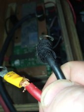
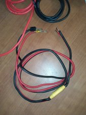
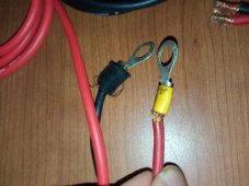
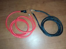
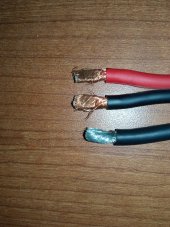
This evening, very shortly, I will be swapping out the 8AGW for a 2'6AWG, and tomorrow I will take readings from morning to night.

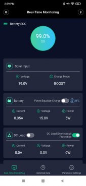
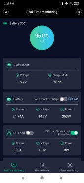
What is your system configuration, and what are the readings at the terminals of your battery and scc? what is your daily usage scenario, and your battery state of charge?

Can you please look at this thread, and if you, or someone you know has a qualifying system, can you take the readings, it would go a long way to building a real world datasheet - thanks again

You need a fuse on the SCC line near the battery
 
BTW, I lost count on how many times OP says "I hate to tell you this, but you are not correct."
Yes, good to see the OP is on the right track now with so many helpers with experiences and knowledge to help.
I hate to tell you this, but you are incorrect.

Laugh Out Loud, I'm just joking, I couldn't help myself, sorry & thank you

Hey, if you have a qualifying system can you post your readings - thanks again

 
Well with any high current charge source sensing is required.
That is a pretty bold statement. I'd guess there are thousands of off-grid homes, mountain cabins, and sailboats that have somehow escaped this requirement. Can you point to where this requirement is documented? Is it international?
 
This guy is entertainment.
I don’t dare get in the middle of this one..
Hey, if you can, if you have a qualifying system, can you give your readings. Ideally, make sure the readings are at peak sun, and your battery state of charge is low, below 70% - closer to 50 or even 40% SOC would be even better - thank you for your interest in this, thanks again

 
Quit it!
Why would a larger data poor of other's voltage drop help you?

You are wasting time with this attempt to gather data. Your system has a voltage drop, you have been given instructions on how to find it.
Okay. How do you account for the Vdroop from 19v to 15v from my panels to the charge controller? Those wires are also in spec and industry standard. That is a massive vdroop, the wires are fine, and I am getting 95+% available amps into my battery and it is the hottest time of year.

How do you explain it? Is it just my system? Is it the same with your system, how do you know, how do I know, how does anyone know?

And why are you resisting the concept of people taking readings and comparing them and logging them to create a real world database?

I do not understand your resistance to this, and it IS important, because if it turns out what many are saying is incorrect, it is not an attempt at anything other than to move in the right direction, get more energy out of existing systems and fine tune the charging parameters to be as efficient as possible - that is the only purpose of this exercise.

See Img5 - this is the Panel Voltage without current flowing: Panel Voltage is 19v
See Img6 - this is the Panel Voltage with Charging enabled and current flowing: Panel Voltage is 15.2

With real world data from a large data set, we can see clearly if the "theoretical" data most people are preaching is true or not.

If it is true, how can you prove it? If it is NOT true, how can you prove it. A large user data set is required - and that is why I am asking for people to make the readings on their own system, something I would think had been occurring and being tracked by such an astute great community like yourselves, and if there was new or conflicting information, I would think the priority was to uncover the true underlying cause or discrepancy and not try to hold onto some dogma that doesn't even have anyone in the communities name on it.


Attachments

  • Img5.jpg
    Img5.jpg
    118.2 KB · Views: 1
  • Img6.jpg
    Img6.jpg
    118.9 KB · Views: 1
Well with any high current charge source sensing is required. My alternator and mains charger have it too.
We are trying to help a user figure out a voltage drop issue and it is pretty clear his Chinese charging controller has no sense leads so how is that relevant?
 
Whelp, Partials Concession Speech: I was partially wrong. I'm on it - I will update the post as soon as I have the pictures moved to the computer
 
That is a pretty bold statement. I'd guess there are thousands of off-grid homes, mountain cabins, and sailboats that have somehow escaped this requirement. Can you point to where this requirement is documented? Is it international?
What I mean is that in any high current situation you will have voltage loss and it things like lithium charging detecting accurate battery voltage is essential

These days it’s easily done if you select your equipment properly , my alternator has battery sensing , and my Ve.smart Victron system networks the battery voltage , battery current and battery temperature to Victron charge sources.

Otherwise you get into real problems ( like the OP) where your charger setpoints are very incorrect because of the maximum voltage drop at high currents also means thd settings are then wrong for lower currents
 
Whelp, Partials Concession Speech: I was partially wrong. I'm on it - I will update the post as soon as I have the pictures moved to the computer
People have been telling you for pages it’s voltage drop nothing to do with “ charging the line” nonsense , “ ye canna change the laws of physics , captain “
 
Hey, if you can, if you have a qualifying system, can you give your readings. Ideally, make sure the readings are at peak sun, and your battery state of charge is low, below 70% - closer to 50 or even 40% SOC would be even better - thank you for your interest in this, thanks again

But you don’t have a qualifying brain. So what’s the goal here. ☺️
 
Whelp, Partials Concession Speech: I was partially wrong. I'm on it - I will update the post as soon as I have the pictures moved to the computer
Edit: Okay, so there are a couple things that I noticed that VERY WELL COULD BE CAUSING Voltage Drop on the line from the Charge Controller to the Battery

First Picture: Janky Wire Connectors, do not look to be copper, maybe aluminum - Also, a couple strands are not in the connector
(Did a Scratch Test - they ARE copper, but they don't have a lot of "meat on them"

Second Picture: This is the wire that was connecting my SCC to the Battery

Third Picture: This is another look at the Connectors that connected the SCC to the Battery

Forth Picture: This is a set of High Quality Thin Strand Tinned Silicon wire that I was using to connect the Main Busbar to the 12v Fuse Panel - I will cut and use a part of this to run the SCC to the battery. Will still have to use the Busbars because my custom made battery does not have "studs" and has 2 large 2' #2AWG wires that need to connect to some type of post/stud. But I will run the test with nothing else on the line, so from the SCC will be a 2' run of High Quality #8AWG cable, connected to the 250 Amp Busbar, and that will connected to the battery with the mentioned #2AWG Cables. There will be absolutely nothing else on the system.

Fifth Picture: I may be crazy, but does it look like the upper Red/Black copper wires are slightly thinner than the High Quality Tinned #8AWG wire? They may be a little thinner then what is spec, or maybe the tinned wire is a little thicker because of the tinning?
[EDIT] OH SHT! Those are Copper Plated Aluminum or somesht it looks like!!!
 

Attachments

  • 8-27-22Image001.jpg
    8-27-22Image001.jpg
    75.4 KB · Views: 20
  • 8-27-22Image02.jpg
    8-27-22Image02.jpg
    146 KB · Views: 19
  • 8-27-22Image03.jpg
    8-27-22Image03.jpg
    214.7 KB · Views: 21
  • 8-27-22Image04.jpg
    8-27-22Image04.jpg
    203.5 KB · Views: 20
  • 8-27-22Image05.jpg
    8-27-22Image05.jpg
    226.4 KB · Views: 20
Status
Not open for further replies.
Back
Top