diy solar

diy solar

Looking for opinions on my solar diagram!

Found another problem. The busbar down below says max amps of 210 @ 12v and 20a per connection. So each connection can only supply 20amps? That must be based and the depth and width of busbar. I am making my own busbars for my battery bank its 8 12v 100ah batteries. 2 batteries in series to give me 4 sets of 24v 100ah going to a pos and neg busbar. My problem is i need to make sure each battery only gets no more than 20amps. Do i need to fuse each line to limit it? There is a total of 80 amps flowing through the busbar. Would my batteries split it up evenly between themselves? Or could 80amps accidentally travel through 1 battery?

 
Last edited:
I'm not sure I'm understanding your question perfectly, but maybe this will help:

So the C-rate is relative to the battery capacity in amp-hours. A charge rate of C/10 for a single 12v 100Ah battery is 10A, if you connect two 100Ah batteries in series your charge rate is still C/10 and your C/10 for a 24v 100Ah battery is still 10A (but remember at 24V that's twice the power--240W vs 120W for the single battery), connect 100 100Ah batteries in series and C/10 will still equal 10A but 10A at 1200V = 12,000W.

Does this make sense? Basically the same rules of series and parallel connections still applies (series = voltage increases, parallel = amperage increases).

If you are referring to the lead acid capacity ratings based on different C-rates, my advice may not apply, its not a subject I know anything about.
 
So the C-rate is relative to the battery capacity in amp-hours. A charge rate of C/10 for a single 12v 100Ah battery is 10A, if you connect two 100Ah batteries in series your charge rate is still C/10 and your C/10 for a 24v 100Ah battery is still 10A
So i got 4 sets of 24v 100 batteries(two 12v 100ah in series). So i should supply no more than 40 amps to the busbar? c10 x 4 sets= 40amps. is that correct?
 
You have 400ah at 24v. 1C = 400amps (charging at 24v).
1C= 400amps? so i can give my battery busbar 400amps and i'll be fine? tic tac said i shouldn't give my batteries too many amps. My batteries are connected to busbars. Problem is i got 2 arrays to one battery bank and its supplying a whopping 80 amps to my busbar at 24v. Since i got my batteries (8 x 12v 100ah) 2s4p there still only c10 a piece. Which is 400ah @ c10. 10a x 4 = 40amps. so supplying 80amps would hurt my batteries. Anyone know if this is correct?

I just found out that the scc restricts the amps with different charge settings. Is that correct? Bulk gives more amps then absorbtion and float?
 
Last edited:
1C= 400amps?

If you have a 400Ah battery, then yes, 1C is 400 amps. If you have a 1Ah battery 1C is 1 amp. Remember C rate, is a ratio, it is expressing charge or discharge rate relative to battery capacity.

1C = the rate at which your battery would be fully charged or discharged in an hour
2C = ... 30 minutes
4C = ... 15 minutes
C/2 = ... 2 hours
C/5 = ... 5 hours
C/10 = ... 10 hours

C/2, C/5, C/10 are also commonly (and more clearly expressed as 0.5C, 0.2C, 0.1C respectively)


so i can give my battery busbar 400amps and i'll be fine?


If your busbars are rated for 400A then they will be fine. Don't worry about C-rate for anything other than the batteries.

I think you are getting confused with C-rates, they are only really relevant to your batteries, nothing else. Amperage is whats important for your busbars, your wires, etc. Best practice for long life for Lifepo4 ('lithium') batteries is <0.2C, still good is <0.5C and <1C is acceptable but not ideal. If you have a 400Ah battery, those rates = 80A, 200A, and 400A respectively. If you don't have lifepo4 batteries, ignore all this, its not relevant to lead acid.

Since i got my batteries 2s4p there still only c10 a piece. Which is 10a x 4 = 40amps.

Yes, and you can think of it in even simpler terms, for the purpose of calculating C-rate just think of it as one big 400Ah battery

tic tac said i shouldn't give my batteries too many amps. My batteries are connected to busbars. Problem is i got 2 arrays to one battery bank and its supplying a whopping 80 amps to my busbar. Since i got my batteries 2s4p there still only c10 a piece. Which is 10a x 4 = 40amps. so supplying 80amps would hurt my batteries. Anyone know if this is correct?

Tictag is right, but 40A charge rate for a 400Ah battery bank (0.1C or C/10) is not going to be a problem regardless of whether you are using lithium or lead acid (though with lead acid I believe the slower you charge and discharge the more capacity you have, so a battery might be 100ah at C/20 but only 90ah at C/10, but I don't know much about lead acid). The most important thing is to make sure all the components in your system can handle the current that will be passing through them.
 
Last edited:
Tictag is right, but 40A charge rate for a 400Ah battery bank (0.1C or C/10) is not going to be a problem regardless of whether you are using lithium or lead acid (though with lead acid I believe the slower you charge and discharge the more capacity you have, so a battery might be 100ah at C/20 but only 90ah at C/10, but I don't know much about lead acid). The most important thing is to make sure all the components in your system can handle the current that will be passing through them.
The batteries are C/10 rated. so 40amps is acceptable. My problem is i got 80 amps going to the batteries. Is that a problem? I got 2 arrays each array is supplying 30v at 40a roughly. Both go to one battery bank(24v 100ah x 4 sets). So there are 80amps going to the battery busbar. is that a problem?
 
The batteries are C/10 rated. so 40amps is acceptable. My problem is i got 80 amps going to the batteries. Is that a problem? I got 2 arrays each array is supplying 30v at 40a roughly. Both go to one battery bank(24v 100ah x 4 sets). So there are 80amps going to the battery busbar. is that a problem?

Can you link to where you read that about your batteries, or post a screenshot or quote?

Is that a problem?

In general I would say always give more weight to the manufacturer specs than to advice from individuals, unless they are trained professionals, or you have very high confidence in the advice you are receiving, and speaking for myself, I'm trying to help you as best I can, but you shouldn't high confidence in my advice alone without confirmation elsewhere.

That said, I think its quite likely that the way your battery manufacturer is using the term C-rate and the way you are thinking about it are different, if you can show me where i read that we can get to the bottom of that.
 
Can you link to where you read that about your batteries, or post a screenshot or quote?
The batteries don't say they are c/10 rated i just said that as a reference. Tic tac said battery manufacturers charge their lead acid deep cycle batteries at c/10. For 24v 400ah bank (8 x 12v 100ah 2s4p) is 80 amps too much?
 
The batteries don't say they are c/10 rated i just said that as a reference. Tic tac said battery manufacturers charge their lead acid deep cycle batteries at c/10. For 24v 400ah bank (8 x 12v 100ah 2s4p) is 80 amps too much?

Maybe @tictag can confirm but my guess is that he is referring to the discharge that they base their amp hour rating on. For lead acid, the slower you discharge your batteries the more Ah you get out of them

If that's what he was referring to than, its not really a hard limit, it just refers to what the battery capacity was tested at. In other words a C/10 rating = "100Ah capacity based on a 0.1C discharge rate" if it was a C/20 rate it would be >100Ah and if it was a C/2 rate it would be <100Ah.

I'm not sure if this is what he is referring to or not, and as I said, I don't know a lot about lead acid.
No tictac and I were talking about how many amps the batteries should get. 12v 800ah c/10 = 80 amps. So he suggested a scc to limit it to 80amps. Problem is i'm doing 2s4p which gives me 24v 400ah at c/10 is 40 amps. So giving it over 40 amps at 24v ish is bad. I'm just theorizing idk if its 40a or 80a. I dont know anything. I do know i got 80 amps going to my battery busbar from 10 panels all wired in paralell for 36v and 80a. My pwm scc will bring the volts down but won't touch the amps as far as i know. I'm really confused. Our conversation is down below.

Abell said:
Do i need to make sure the battery doesn't get too many amps? they are flooded 12v 100ah lead acid deep cycle batteries 240amp draw.
Tic tac said:
Yes. Lead-acid batteries generally speaking have a C/10 maximum charge rate (some AGMs allow up to C/5), which for your battery bank that's 80A (800AH / 10 = 80A). You should not regularly exceed this to avoid premature aging.
 
Ah, yes I see, so it is in relation to battery life/longevity. Have you bought your batteries yet? or decided on a brand/model? If so, I would check what its rated for. I never realized C-rate was such an issue with Lead Acid
 
Those math symbols and equations really hurt my head. It would take me eons to figure out how to calculate it myself. All i really wanna know is the 400ft of 12 awg wire to pv bus 36v 8a how much watt loss to heat?
This is an interesting question, though most people simply ensure that there is no more than a 3% voltage drop across any one cable run, this ensures minimum power loss across the system as a whole. But for shits and giggles, let's do this!

Firstly some assumptions:
  1. A PV cell/module/panel can be thought of as an ideal constant current source in parallel with an ideal diode under normal conditions. There are both shunt and series resistances for cell/module interconnections, but this is overly complicated for our purposes.
  2. Kirchoff's Voltage Law tells us that all voltages in a circuit must sum to zero, therefore power loss need only be represented by P = I²R, where R is the sum total resistance of the circuit.
  3. A high capacity battery can be thought of as an ideal constant voltage source with a series resistance. There is an RC component but again this is overly complicated for our purposes. Because of point (2.) we can ignore the voltage aspect and to a large extent the series resistance during the Bulk charging stage i.e. during Bulk, the battery presents a very low resistance to any charging supply. In short, we can ignore the battery.
  4. A PWM SCC during Bulk charge can be thought of as a ideal switch i.e. an ideal short circuit
Therefore, the whole circuit can be simplified down to a constant current source in series with a load resistance, which in this case, is the resistance of all cables and connectors:
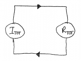
equivelent.png

...where:
ITOT = Isc array 1 + Isc array 2
ITOT = 8.85A + 8.85A
ITOT = 17.7A

and...
RTOT = 2R1 + 2R2 + 2R3 + 2R4 + 2R5 +2R6

.. where:
R1 = Resistance of PV panel-to-busbar1 cable
R2 = Resistance of busbar + connections
R3 = Resistance of busbar-to-SCC cable
R4 = Resistance of SCC-to-busbar2 cable
R5 = Resistance of busbar2 + connections
R6 = Resistance of busbar2-to-batteries

..........

Future me.... I was going to work this out for you but I'm struggling with time at the moment.

To work out the resistance of any cable, refer to here. If you want to work in feet, click the 'ohm/1000ft' at the top. Then just take the number, divide by 1000 to get resistance per foot, then multiple by the total run length i.e. there and back. Resistances of large gauge cable will be in mΩ (thousandth's of an Ohm).

To work out the final power loss, the formula is just P(loss) = I²R, for example, if your total resistance turned out to be 10mΩ, total power loss would be: P(loss) = 17.7A² x 10mΩ = 100W

Good luck with your calculations!
 
Lets say my 2 arrays are putting out the same volts but different amps. When they go to the same battery bank will a inbalance of amps make my battery's inbalanced? Lets say 1 array is putting out 30 amps and other is 40 amps. So when they hit the battery busbar. The busbar itself combines the 2 for 70 amps. So in theory there would be no inbalance? Man i feel stupid sometimes lol.
It doesn't quite work that way. Imagine electrical current being a flow of water splitting into different pipes. The water doesn't 'decide' where it goes, the physical properties of the pipes determine that - for thick pipe, more water flow, for a very thin pipe, very little water will flow. The 'thickness' in this analogy is a metaphor for 'electrical resistance'. A discharged battery has a lower resistance than a fully charged battery, more 'water' will flow into it because it represents a thicker pipe.
 
I just realized my morningstar scc 45a pwm have a input, battery, and output terminals. If i connect my scc directly to the inverter through the output it will make sure my batteries don't get over drained.
No, do not do this. Most SCCs take power for it's own circuitry from the battery, if you don't have a battery connected to the battery terminals, and it disconnects the 'load' terminals under low PV conditions, your SCC will just switch off forever.
 
Well i didnt ask morningstar but found a document of theirs saying never hook inverter to any of their scc in a battery based system. Which is stupid.
I agree. All SCCs are connected to the inverter because the inverter is connected to the battery!

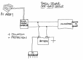
basic solar.png

what can i hook up to the output? maybe i can do the 12v fuse block and 12/24v outlets?
Yes, those SCCs with a 'load' terminal are designed to power non-essential loads i.e. those that can be disconnected when the sun isn't shining. I've personally never found a use for this feature but I'm sure others have (or why would they develop such a product feature? Rhetorical).
 
Just found a low voltage shutdown relay to go from battery bank to inverter. It says its 100a. But I have 8 x 12v 100ah batteries. Its a 24 volt system and i would rarely or never exceed 100a to the 24v 2500w inverter. Anyone know if it works or do i need one for each battery?
You should always design your system for the rated output of your components - just because you don't imagine you'll use it now, you may in the future. A 2,500W inverter would draw 104A from a 24V battery bank, twice or even three times that under surge e.g. A/C units, Microwaves etc. A 100A relay would not be suitable.

Personally, I would use the inverter's own low voltage disconnect then use something like a Victron BatteryProtect (don't want to sound like a Victron fan-boy!) to disconnect your other DC loads:

dc system.png

The challenge is that, whilst a large capacity battery can be thought of as a constant voltage source, even the biggest banks do tend to dip under heavy loads. A 50% SoC lead-acid battery should have a no-load terminal voltage of around 12.1V (22.2V for a 24V(nominal) battery) but if you set your low voltage disconnect at exactly 22.2V, a heavy load at say 60% SoC might well disconnect the inverter prematurely. Go too far below 22.2V, though, and you risk discharging your battery below 50%. Grrrr.

You might need to do some personal testing. Go for a 22V low voltage disconnect then hammer your battery until the inverter disconnects. Disconnect your loads, wait for your battery to stabalise (an hour or so) then check the no-load terminal voltage - this will give you the state of charge your inverter disconnects at. If it's 50%, you're done - nailed it! If not, lower the the low voltage disconnect by the difference between 22.2V and the measured terminal voltage. This will then ensure that your inverter will disconnect at 50% SoC even under heavy loads.

Edit: Corrected typo
 
Last edited:
Got a question! Very important!! If i have two 12v 100ah batteries and they have a c10 charge that would mean they can only take 20amps togethor. If i put them both in series for 24v 100ah is it still 20amps or 10amps? Does the c10 stay the same or get doubled? I'm confused.
A 100AH 12V in series with another 100AH battery would give you a 100AH 24V battery, so a C/10 charge rate limit would limit each battery 'string' to 10A.

Think of it another way, if you have 10A flowing through a circuit, 10A is flowing through that circuit everywhere - it doesn't 'slow down' in parts (terrible analogy, but, whatever...) - so 10A will be flowing through both batteries. If any one battery has a C/10 charge rate limit, then you should only permit 10A to flow whether you have two connected in series or 1,000 connected in series.
 
My problem is i need to make sure each battery only gets no more than 20amps. Do i need to fuse each line to limit it?
No, fuses are ONLY there to protect the connecting your devices from a short circuit fault condition. It is your system design that must limit the charge current to within any charge current limit.
There is a total of 80 amps flowing through the busbar. Would my batteries split it up evenly between themselves?
Yes, assuming they are all at similar state of charge, which they should be. 20A is not a lot of current in these systems, I would urge you to consider upgrading your busbars. My busbars are rated for 250A and each stud is 9.5mm in diameter (yours are 4 or 5?) and I only have a 1,600W inverter!
Or could 80amps accidentally travel through 1 battery?
It is possible though only under a fault condition. If, for example, a battery were to develop an internal cell-short (through a battery aging process called 'active material shedding') then its internal resistance would effectively drop to near zero, meaning more current would flow through it via your busbars. But this is highly unlikely.

Edit: 'shirt circuit', lol! Corrected typo.
 
Last edited:
Back
Top