diy solar

diy solar

JK-BMS-CAN with new Cut-Off Charging Logic (open-source)

Sleeper85

Sunday handyman
Joined
Nov 28, 2022
Messages
421
ESPHome component to monitor a Jikong Battery Management System (JK-BMS) and communicate with inverters supporting CAN bus protocol compatible with Pylontech, GoodWe, Seplos, SMA or Victron.

It's with pleasure that I announce the new version of the JK-BMS-CAN open-source project with the new Cut-Off Charging Logic.

Thanks to @shvm for creating the Cut-Off Charging Logic equations.

Thanks to @MrPablo for programming the Auto Charge/Discharge Current Control and Auto Charge Voltage Control functions to avoid OVP/UVP alarms.

Thanks to @arzaman for testing with Atom S3.

I hope you like it ;)

Edit 04.03.204 :

I would like to tell those who are interested in a multi-bms version not to buy too much ESP32 or other hardware in advance. If we want to get it right, it's more than likely that a dedicated PCB will be required.
 
Last edited:
All the hard work you have put into making this release possible is nothing short of amazing!

Best wishes, and enjoy quality time ahead on your trip. Now is the time to celebrate! 🥳🥳
 
Thanks @Sleeper85! Enjoy your trip!

Regarding the new Auto Charge/Discharge Current Control, this feature has been introduced to hopefully prevent OVP and UVP alarms.
At a high level, the ESP will check the maximum and minimum cell voltage every refresh cycle, compare it to a BMS threshold and automatically reduce current as needed. This should reduce voltage spikes and drops.

As with most things though, the actual implementation is more complex than that!

In the YAML, there are two configuration settings, one each for Charge and Discharge control.
The values within are commented and should be fine at the default values.
2 new switches have been added, 'Automatic (Dis)Charge Current'. When disabled, maximum allowable current will be as per the existing sliders, otherwise the new logic below will be used.

First, an instantaneous allowable current is calculated based on maximum / minimum cell voltage, referencing the new parameters, as well as BMS values for cell over / under voltage release.
I've used the release values as I'd prefer to leave a buffer before a cell could hit OVP or UVP.

A moving average is then used to smooth transitions between calculated values.
After that, another sensor will return the min of the instantaneous and moving average. This means that the allowable current will always drop quickly, but rise over several seconds. This stops voltage oscillations as current values jump around.

The code used for calculating the automatic current values isn't that intuitive, so I have a link to a google sheet which will show you the impact of changing parameter values.

esphome-jk-bms-can Current Control
 
Last edited:
Enjoy your trip @Sleepers
thanks MyPAblo and the mathematicians for the hard work

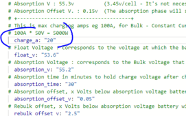
i was just yesterday fighting the OVP where my system was tripping the alarms and i had to reflash to this low to get it to stop complaining
even themn it still complained a bit until i further reduced it to 15
1708681157780.png
the JK was set to 35 amp....and it seemed to ignore both its settings and the JK settings

hopefully this is fixed
and also on the BLE version as i cant get the Wire working still after trying every thing...i am beginging to think ist the BMS version.
 
Enjoy your trip @Sleepers
thanks MyPAblo and the mathematicians for the hard work

i was just yesterday fighting the OVP where my system was tripping the alarms and i had to reflash to this low to get it to stop complaining
even themn it still complained a bit until i further reduced it to 15
View attachment 197749
the JK was set to 35 amp....and it seemed to ignore both its settings and the JK settings

hopefully this is fixed
and also on the BLE version as i cant get the Wire working still after trying every thing...i am beginging to think ist the BMS version.
@chaosnature, you're using a Solis inverter aren't you? What model do you have?

The auto charge current control should prevent OVP, but I know my Solis didn't always respect the requested charge voltage.
 
will the -HC jkbms version that has the CAN protocol work in parallel

I see you guys focusing on the rs458 conversion - writing the inverter protocol for it...what about writing the inver protocol for the CAN port so that the rs489 is free for paralleling?

regards
 
will the -HC jkbms version that has the CAN protocol work in parallel

I see you guys focusing on the rs458 conversion - writing the inverter protocol for it...what about writing the inver protocol for the CAN port so that the rs489 is free for paralleling?

regards
We don't actually use the CAN port on the JK BMS, we only utilise the GPS / UART port.
A likely solution for multi-BMS comms will be to use a standard JK BMS for each battery, each with an ESP32 adaptor board which connect to each other via the CANbus.

Again, there's no timeline on this - implementing dynamic CVL and external shunt support is first on the list as it's easier to test and debug.
 
While we wait for the Multi setup script - this is what i have decided
my BMS is 24s, i have used up 14s from the GBLI5001 leaving 10s to use
that 10s i will spread it amongst the other battery 10s leaving 4s unbalanced

however - the maths is what i cannot do if i continue the series loop i will end up with 48v + 48v - (3.7 x4+) = 81v cells being balanced and 96 total coming out
1708705898013.png

how do i wire this up so that it stays 48v
only thing i can think of is parallel the cells that will be too many wires.
 
While we wait for the Multi setup script - this is what i have decided
my BMS is 24s, i have used up 14s from the GBLI5001 leaving 10s to use
that 10s i will spread it amongst the other battery 10s leaving 4s unbalanced

however - the maths is what i cannot do if i continue the series loop i will end up with 48v + 48v - (3.7 x4+) = 81v cells being balanced and 96 total coming out
View attachment 197791

how do i wire this up so that it stays 48v
only thing i can think of is parallel the cells that will be too many wires.
I don't think you can add additional cells for balancing and monitoring without increasing the total voltage. As you say, that's not something you can do with the Solis inverter.

I'd suggest buying another JK BMS that matches your current one, setting up the second battery with that and you can potentially be the tester for multi BMS logic when I develop it.
 
let's start testing :)
JK2A24S15p x 2

as long as the logic uses the BLE as i did not succeed with the Wire lol
 
let's start testing :)
JK2A24S15p x 2

as long as the logic uses the BLE as i did not succeed with the Wire lol
Ok, but it's quite probable that code won't be available until mid-March - dynamic CVL and external.shunt support is next up.

Regarding the wire version, have you confirmed that you're getting a signal on the wires themselves? You could use a multimeter between TTL ground and the RX then TX lines, just to confirm voltage, etc.

I don't know of anyone else who is getting zero data via the UART TTL port, so I'm pretty sure it's a connection issue.
I decided to Test Both BLE and Wire
Result below:

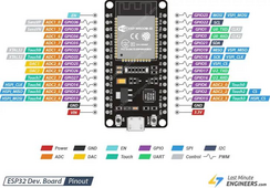
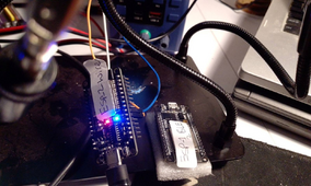
CAN-WIRE - When connected to JKBMS Voltage between:
rx2 (GPIO16) and tx2(GPIO17) = 0.01 (0.5v with broken wire)
rx (GPIO1) and tx(GPIO3) = 0.01 (0.5v with broken wire)
Ground and tx or rx = 3.26
# BMS Light Blinking


CAN-WIRE - When Disconnected to JKBM Voltage between - SAME Result
rx2 (GPIO16) and tx2(GPIO17) = 1.04 (0.5v with broken wire)
rx (GPIO1) and tx(GPIO3) = 0.01 (0.5v with broken wire)
Ground and tx = 3.26
Ground and rx = 2.13


To compare i did:
CAN-BLE - When connected to JKBMS Voltage between:
rx2 (GPIO16) and tx2(GPIO17) = 0v
rx (GPIO1) and tx(GPIO3) = 0.5v
# BMS Light Stable on - Can hear beep when it connects to BMS

CAN-BLE - When Disconnected to JKBMS Voltage between - SAME Result
rx2 (GPIO16) and tx2(GPIO17) = 0v
rx (GPIO1) and tx(GPIO3) = 0.5v


i then checked :
Tx and Rx from the JKBMS Voltage between:
Ground and tx = 3.29 after checking wires (0.0 Wire was broken)
Rx and T = 0.0

1708733213420.png
1708733239001.png


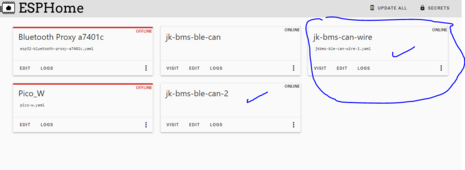
ESPHOMe show online
1708733593500.png
1708733857793.png
 
Last edited:
I decided to Test Both BLE and Wire
Result below:

CAN-WIRE - When connected to JKBMS Voltage between:
rx2 (GPIO16) and tx2(GPIO17) = 0.01 (0.5v with broken wire)
rx (GPIO1) and tx(GPIO3) = 0.01 (0.5v with broken wire)
Ground and tx or rx = 3.26
# BMS Light Blinking


CAN-WIRE - When Disconnected to JKBM Voltage between - SAME Result
rx2 (GPIO16) and tx2(GPIO17) = 1.04 (0.5v with broken wire)
rx (GPIO1) and tx(GPIO3) = 0.01 (0.5v with broken wire)
Ground and tx or rx = 3.26


To compare i did:
CAN-BLE - When connected to JKBMS Voltage between:
rx2 (GPIO16) and tx2(GPIO17) = 0v
rx (GPIO1) and tx(GPIO3) = 0.5v
# BMS Light Stable on - Can hear beep when it connects to BMS

CAN-BLE - When Disconnected to JKBMS Voltage between - SAME Result
rx2 (GPIO16) and tx2(GPIO17) = 0v
rx (GPIO1) and tx(GPIO3) = 0.5v


i then checked :
Tx and Rx from the JKBMS Voltage between:
Ground and rx = 3.36
Ground and tx = 3.29 after checking wires (0.0 Wire was broken)
Rx and T = 0.0

View attachment 197896
View attachment 197897


ESPHOMe show online
View attachment 197898
View attachment 197902
1708733946009.png
 
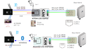
Also, I'd like to add my two cents to this amazing project.

I've prepared a summary connection diagram for those who are going to use the M5Stack—a nice product that simplifies the wiring and connections, making the hardware part almost plug and play.
Both configurations have been tested and are stable

1708805763061.png
 
Back
Top