diy solar

diy solar

Cabinet busbars and standoffs

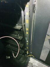
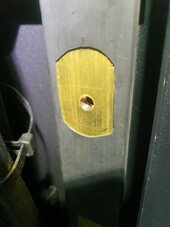
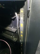
The standoffs are not an issue, but if the buss bars are brass instead of the nickel plated copper in their sales info, you need to give them a call.

perhaps Ben@fogstar might wish to comment via this thread, as he is on our forum.


I will be giving them a email directly, only my last email to Fogstar regarding battery paramotors got ignored.

a little bit frustrating seeing as ive spent over £4.5 grand with this firm in the uk (Fogstar)
 
perhaps Ben@fogstar might wish to comment via this thread, as he is on our forum.


I will be giving them a email directly, only my last email to Fogstar regarding battery paramotors got ignored.

a little bit frustrating seeing as ive spent over £4.5 grand with this firm in the uk (Fogstar)
What are the dimensions of the busbar?
 
Just a up-date

Ben was good enough to respond to my Email today (a Sunday)
he said he was happy to send me out the copper bus bars
 
from what I gather, fogstar used brass to help with thread stripping in the brass
I will assume you meant thread stripping in copper. In that case they should have gone more narrow and thicker rather than switching to brass and still advertising copper. Bad PR to get caught with the hand in the cookie jar so to speak. I will be interested to see the diminsions of both brass and copper and if they are the same or if they increased the size of the brass bars to compensate for the inferior metal.
 
You are looking for something like this, right?
That is what I was looking at and the only thing that is important about it is the voltage rating. With the sort of DC you are dealing with you aren't going to start an arc. Now from a pure physical standpoint a taller standoff might make it easier to reach behind to hold a nut or something if you manage to strip a threaded hole and don't have a tap handy.

The main thing is to not have the bars near enough to anything to physically short them to it. I assume your cabinet came with the finger molded plastic around them and a cover? If not I think that is a worthy investment since it only costs $20ish for 8ft.
 
I will assume you meant thread stripping in copper. In that case they should have gone more narrow and thicker rather than switching to brass and still advertising copper. Bad PR to get caught with the hand in the cookie jar so to speak. I will be interested to see the diminsions of both brass and copper and if they are the same or if they increased the size of the brass bars to compensate for the inferior metal.

I am yet to go to my workshop where my cabinet is, BUT from memory, I would say the brass buss bars that I have in my cabinet are one and a half inch wide (38mm) and about 10mm thick.

as promised, I will defiantly confirm this and upload a photo.

I have been promised some free solid copper bus bars, and when I get them, I will compare.

there is a buss bar calculator floating around on the net.
 
That is what I was looking at and the only thing that is important about it is the voltage rating. With the sort of DC you are dealing with you aren't going to start an arc. Now from a pure physical standpoint a taller standoff might make it easier to reach behind to hold a nut or something if you manage to strip a threaded hole and don't have a tap handy.

The main thing is to not have the bars near enough to anything to physically short them to it. I assume your cabinet came with the finger molded plastic around them and a cover? If not I think that is a worthy investment since it only costs $20ish for 8ft.

No finger plastic. I know the ones you mean though.

my brass bars are covered in heat shrink (as per the description I gave above)
 
As promised

Brass bus size as per my cabinet

38mm x 5mm thick

A few photos as well as requested
 

Attachments

  • 20240313_143610.jpg
    20240313_143610.jpg
    146.7 KB · Views: 8
  • 20240313_143556.jpg
    20240313_143556.jpg
    114.8 KB · Views: 8
  • 20240313_143552.jpg
    20240313_143552.jpg
    146.6 KB · Views: 8
So, using the calculator - the brass if it was best quality was 760amp capacity and if it was cheaper quality (low copper content) it was 380amps. For the copper ones carry around 942 amps.

Much better deal with copper. They did increase the size of the brass verse copper but IMO not enough.
 
I made my own from 1/4" x 1 1/4" copper bar. Nickel plated it myself.

View attachment 201893

Cold headed in the square holes for carriage bolts.

View attachment 201894


Insulators are these from Amazon, 3 per busbar. https://www.amazon.com/gp/product/B009SCSXVO/ref=ppx_yo_dt_b_search_asin_title?ie=UTF8&psc=1


Calculator says yours are good for 1000amps.... does that agree with your calculations? I assume the red cable is from a battery and you intend to hook up your load to the other end of the class T fuse?

Looks like your bar to the class T is much smaller than the bus bar itself?
 
Calculator says yours are good for 1000amps.... does that agree with your calculations?

Probably when I built it. That has been about 1.5 years ago. I know it is way oversized, I like things on the heavy side. Cabinet build is in my signature below.
I assume the red cable is from a battery and you intend to hook up your load to the other end of the class T fuse?
You have the current backwards.

4/0 Red cable goes to battery bank ABB shunt trip breaker controlled the Batrium BMS. From ABB breaker the cables go to a Victron Lynx and split to the 2 inverters. Another 250A Class T fuse for each inverter feed. Seen here in the wiring trough.

1710344785019.png

Looks like your bar to the class T is much smaller than the bus bar itself?
That is a 175A Class T fuse that goes from battery to main busbar. I would have used some cable but space was tight and I decided this way I could get everything to fit. I have 4 batteries connected to the main busbar.

Next box I am building is deeper so I might run cable or maybe busbars from batteries and T fuses to main busbar which will be 1/4" x 1 1/4" again.
 

diy solar

diy solar
Back
Top