Quattrohead
Solar Wizard
Can JBD be the next BMS to integrate please 
I would expect that's doable with the syssi code for jbd and @Der_Hannes mqtt code...Can JBD be the next BMS to integrate please
In that matter, I think you guys need to keep it simple and modular, and also cheap. No fancy new boards etc, just one ESP32 per battery pack, one for the inverter and join all the data via LAN.MultiBMS support is on the list for development in the next version, which @Der_Hannes has been involved with.
@Sleeper85 has been working on reconfiguring the code so it's more modular, making it possible to 'plug in' different functions like displays, multiBMS, etc.
In that matter, I think you guys need to keep it simple and modular, and also cheap. No fancy new boards etc, just one ESP32 per battery pack, one for the inverter and join all the data via LAN.
Just ... WowThis is what is being considered today.
In addition I will integrate it into PVbrain2.
The goal is to work as a team with code that is modular and can be adapted to several solutions.
Just ... Wow.
I actually was planning on doing my own Strategy controller (Energy Balance) in Docker/Podman container using Python since I would need to control the charger separately anyway.
In my case, I guess I just want multi-bms communication. Relay control I guess anybody can just throw a sonoff or smth like that in as well if it wasn't part of the core hardware anyway.
But I'm sure this will be liked by many people as an all-in-one solution. Keep it open and no ultra-expensive boards please, just like you have now.
I'd rather make some small donations here and there rather than having to pay 300$ for a board or something like that. Many people (DIY) will for sure be on board with that. For the other people, you can "target" them with an off-the-shelf (or almost) solution.
ThanksRest assured, we are all in line with the open-source philosophy. Even PVbrain2 is open-hardware but it still costs +/- $100 to print the board with all the components soldered. In addition there will be a “Peter Board” style solution.
Finally this still needs to be discussed within our group.


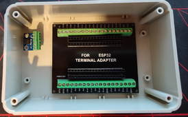
If I were you, I'd use the Atom S3 lite + CAN combo.Or maybe lazy man's approach like this?
View attachment 203027
EDIT 1: doesn't really work as this piece of junk doesn't align properly (had to bend the pins of the ESP32 to fit it into the socket) ...
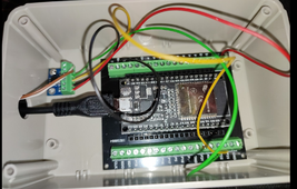
EDIT 2: Not pretty but could do it
View attachment 203050
Digikey has already shipped the CAN hat for the Atom S3 Lite though ... Uhm ... What to do now
MultiBMS support is on the list for development in the next version, which @Der_Hannes has been involved with.
@Sleeper85 has been working on reconfiguring the code so it's more modular, making it possible to 'plug in' different functions like displays, multiBMS, etc.
Yes you got me right - every slave needs to have that last will topic so the master can recognise if its available or not
I want to share my personal fork of syssi´s repo which is fully configured to work perfect with iobroker.
So all the topicsv of the slaves are in a certan order / structure....i was not happy with the default mqtt structure of esphome like /sensor/name/state
mine look like this:
View attachment 202206
I was trying to compile now with my hack solution but ... yeah ... it's ugly. And the non-isolated CAN makes me unease. I agree, the Atom S3 Lite + CAN is a nice combo. Also the RS232/RS485 HAT looks damn interesting. It's tiny !If I were you, I'd use the Atom S3 lite + CAN combo.
We're using that for internal testing and it's a slick, isolated CAN setup.
Well... This software is based on syssi software which also support AFAIK the jk inverter bms. Therefore that makes it jk bms (or also potentially with other brands) agnostic, I. E. They should all work, once they add support for multi bms communication I think.Upon reading more about this, it seems this is focused more on older hardwares.
Is there any way you could support the JK Inverter BMS variants, especially it already has paralleling support, so maybe poll only from master bms? I would prefer your charging/discharging logic than the factory one. Yes, they have float mode and such, but everything is on timer. And it doesnt have the voltage offset for Deye's problem, and the flexibility of changing settings on the fly with HA or Web.
I'm sure some people are willing to donate for this, I'm one of those. If you got the energy to consider this, just private message me.
Upon reading more about this, it seems this is focused more on older hardwares.
Is there any way you could support the JK Inverter BMS variants, especially it already has paralleling support, so maybe poll only from master bms? I would prefer your charging/discharging logic than the factory one. Yes, they have float mode and such, but everything is on timer. And it doesnt have the voltage offset for Deye's problem, and the flexibility of changing settings on the fly with HA or Web.
I'm sure some people are willing to donate for this, I'm one of those. If you got the energy to consider this, just private message me.
Well... This software is based on syssi software which also support AFAIK the jk inverter bms. Therefore that makes it jk bms (or also potentially with other brands) agnostic, I. E. They should all work, once they add support for multi bms communication I think.
Im happy to hear this.
Support for new range of JK BMS (JK-PBx) · Issue #390 · syssi/esphome-jk-bms
Hi, Do you have plans for supporting the new range of BMS's from JK e.g. JK-PB1A16S10P?github.com
As @silverstone said the communication with JK-BMS is based on the syssi project.
It seems that support for the new JK-BMS inverter is in the testing phase.
Start by trying to get the syssi project to work with your BMS and if it works then you can use our project.
Hi, sorry for the double post.
Apparently, this repo was able to implement the multibms pulling of data of slaves just using the master bms using 1 esp.
Can we make use of this to implement your charging/discharging logic?
This is great! Let us know how can we help (not coding definitely).I'm putting this on our todo list. It will be simpler with the packaged version which will soon be on our development branch.
If I were you, I'd use the Atom S3 lite + CAN combo.
We're using that for internal testing and it's a slick, isolated CAN setup.
And allow JK-BMS integration with JBD (seen another project done this) - and Consider S3In that matter, I think you guys need to keep it simple and modular, and also cheap. No fancy new boards etc, just one ESP32 per battery pack, one for the inverter and join all the data via LAN.
Yoooooo!! - I can't wait to get home and test this....sounds like many of my issues will be resolved with this updateV1.17.4 has been released on GitHub:

GitHub - Sleeper85/esphome-jk-bms-can
Contribute to Sleeper85/esphome-jk-bms-can development by creating an account on GitHub.github.com
Changelog:
- Added "SMA" to CAN BMS names
- Added function "Auto Charge Voltage Control" to avoid OVP alarms and improve balancing
- Categorised sensors
- Set time source to SNTP
- Min battery voltage based on BMS value
- Added "Last Complete Charge" timestamp
- Renamed daily energy sensors
- Added input number display option (slider or box)
The main feature added to this release is 'Auto Charge Voltage Control'.
When enabled, the requested charge voltage will automatically reduce as cell voltage delta increases - this reduces the chance of cell overvoltage as well as providing more time for cell balancing to occur.
This feature will only be active if cell voltage delta is greater than 5mv (and if 'CAN Automatic Charge Voltage' is enabled).
Thanks go to Matthias U and Stuart Pittaway, creators of the original logic (found here).
For those interested, this logic calculates how much additional voltage is required for the max voltage cell to reach target. It will also compare all other cells, applying a weighting factor that should prevent any cell from exceeding target voltage.
The logic is not easy to grasp, so a helper spreadsheet is available here for scenario testing.
Final note, for any users using this code with a Solis inverter, I recommend setting the CAN protocol and CAN BMS name to 'SMA', then setting the battery name to 'AoBo' on the inverter itself.
This resolves an issue with the Solis implementation of Pylontech control, resulting in more accurate voltage regulation.


