Hi All,
It's great to have the new code with many functionalities. However, when I flash the new firmware, the inverter stop charging and discharging by reducing the current limit to 0. Actually, I forked Sleeper's version a month ago and do some modification on the can id 0x355 to help the inverter continuing charging process when JK report wrong soc so we can achieve 3.45 (at max) for LFP. Also, I made new slider to help user to control on UVP (higher than the number defined in the JK) and OVP (lower than the number defined in JK). I found the Jan version of Sleeper is working better with Luxpower and Deye. 2 days ago, I flash the new code and it seem the inverter stop charging/ discharging if we leave the auto voltage and current switch on.
With the details I have observed on using 3 Luxpower and 3 JKBMS + LFP in a year, I found that:
+ JK has it owned problem on SOC calculation and we can solve this by not posting its SOC when it reported 100% but Voltage is less than 3.45 V, similarly applied for 3.2 or 3.0 (depending on user, i myself set 3.2 as the UVP). Inverter like Lux prefer using SOC than Voltage (Voltage only work if choosing battery interface as lead acid);
+ Charging logic is seem to be difficult to handle. Inverter like Deye or Luxpower seem to have better control on charging with full and smoot CCCV when battery is set as Lead Acid (no Can communication). I am not quite good at programing but I do see the logic that
@sleeper is using but I have not got a chance to leave both (the new yaml config and the own one) to work, I all have to intervene myself at the final stage to reduce the charging current to avoid Inverter alarm (change status to "notice" which is annoy innocent user a bit) and shut off charging.
My proposal: Treat the Battery similarly to what Inverter is treating as "Lead acid" and solve at 2 points
1. Control on SOC reporting - easy as Sleeper has done already: when JK report wrong SOC, keep it at 98 or 99 - Lux stop charging randomly when SOC is 99% but fully stop at 100%;
2. Refine the Charging/ discharging logic by better control on current so that:
>> At charging:
+ CC: Bulk charge can happen any time as set by Inverter and apply 0.3C-0.5C when cell voltage is below 3.42;
+ CV: start and reducing current gradually so when JK SOC hits 100%, current should be low enough to avoid the 3.45 ceiling
+ Floating: When 3.45 is reached, keep the float voltage until the discharging cycle start.
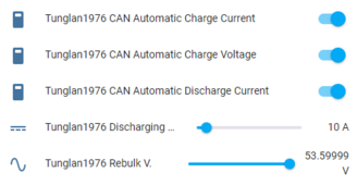
>> At discharging: Better to set the UVP target voltage in software so we can tell the inverter to reducing discharging current limit to lower or even 0 when user defined UVP is reached (minimum cell voltage is lower than the defined UVP value on home assistant)
As I observed my revision on the can_id 0x355: I was not able to revise Sleeper code on the part relating to can_id 0x351 so I decicided to revise the 0x355 part with following checkpoint:
1. Jksoc is alway 98 or 99% when voltage is not yet reaching the OVP level defined by user: so the inverter will continue to charge, of course, i will have to intervene manually here at the final stage to reduce charging current when cell voltage is 3.42. This will automatically help JK to reset its wrong SOC;
2. When Jk report SOC 0% or below the Stop discharging SOC (set in inverter - i.e 25%), but minimum cell voltage is still greater than 3.2 or UVP level set by user, report to inverter the SOC of 26% and start reducing discharging limit, With this we can help JK to discharge to the expected safe level without alarming the inverter.
I will try reading a bit more on how to work with Script to revise Sleeper code to make the charging can be as smoot as expected. Also, some more feature like discharging/charging current by time can be included.
View attachment 203891
My English is not so good but I would like to share my view with you guy for moving forward a better and smarter JKBMS things.
Best
Ngoc


.


 .
.