diy solar

diy solar

Solar powered LTO battery for 5v use below freezing.

Suijuris

New Member
Joined
Jan 31, 2021
Messages
18
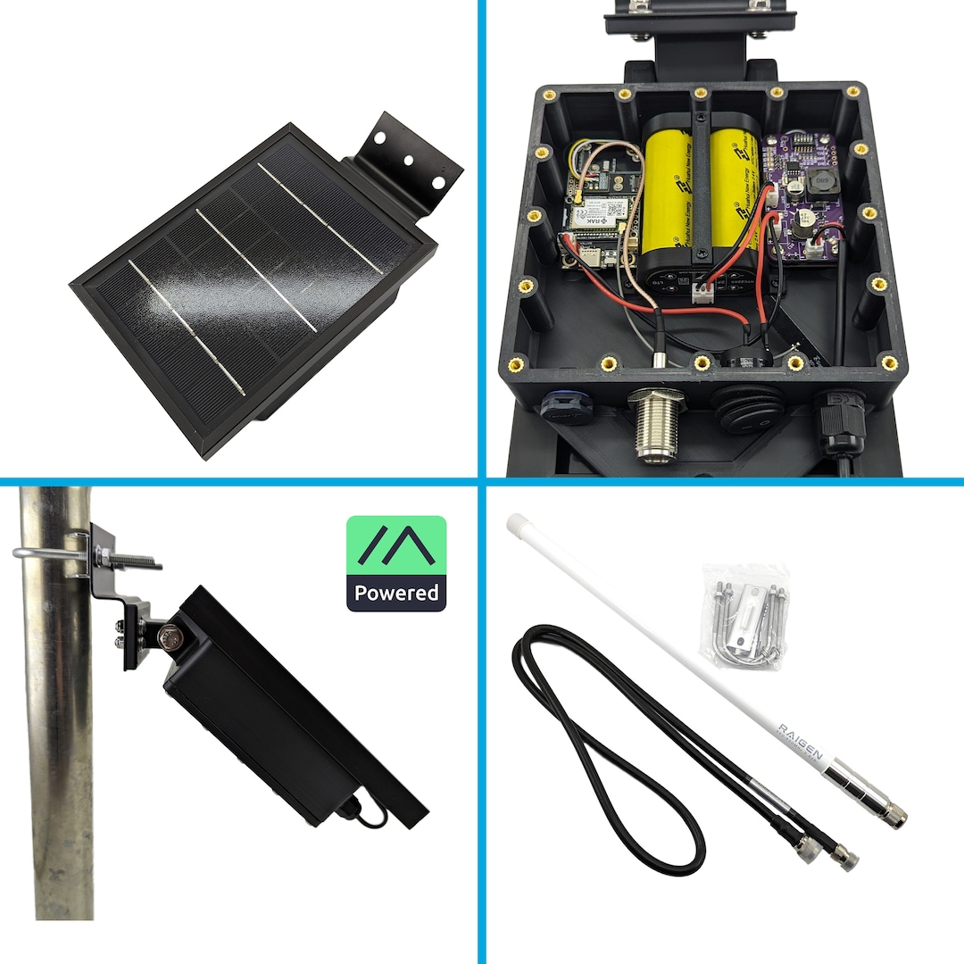
I'm interested in building a solar powered LoRa relay that will work at below freezing temperatures. The LoRa device requires 5v (though somehow they seem to work fine from one 18650). I've considered using two 18650s in parallel, and configuring so that it only charges when above freezing. I've also considered putting it in a thermos, and adding a heating element.

Hypothetically, to build a LTO battery that outputs 5v.. I was thinking of using 4 LTO cells ( 2.4V 3000mAh LTO 23680 Lithium Titanate Cell 15C) in series, and using a voltage regulator to output 5v. Do I need a 4S LTO BMS to do this? Could it be done with 3 cells? I assumed that 4 cells would be better than 3, to output 5v regardless of capacity. I read somewhere that the LTO is so durable that there is a chance that they'd be fine without a BMS. If it wouldn't just be destroying the cells to build without a BMS, could I put 3 cells in series, and have 5v for some part of the battery capactiy? If so, would it simply shut off once it fell below the appropriate voltage, or would it do damage?

Could someone explain to me the considerations for attempting the LTO battery, and the corresponding appropriate solar panel, for this use? Could a 12v panel be used with an approx 9v battery? I notice there are 10v solar panels, as well.

I am open to the idea that a larger capacity LifePo4 battery might be the way to go. My goal is to have uninterrupted 5v power supply through long periods below freezing, and if need be, small solar exposure window. I'd like it to be reliable, and as simple as possible. Even if a LifePo4 setup would result in a better solution, I am still curious how a solar powered LTO battery supply for 5v would be built.
 
Hypothetically, to build a LTO battery that outputs 5v.. I was thinking of using 4 LTO cells ( 2.4V 3000mAh LTO 23680 Lithium Titanate Cell 15C) in series, and using a voltage regulator to output 5v. Do I need a 4S LTO BMS to do this? Could it be done with 3 cells?
I went through all the LTO cell datasheets I have. All the different cell manufactures spec the discharging cut off voltage is 1.5V. 3S would give you 4.5V as a low cut off, likely acceptable for your proposed 5v application, if you can ensure it shuts off at 5V. The cells will not shutoff without a BMS or some external system
I read somewhere that the LTO is so durable that there is a chance that they'd be fine without a BMS. If it wouldn't just be destroying the cells to build without a BMS, could I put 3 cells in series, and have 5v for some part of the battery capactiy? If so, would it simply shut off once it fell below the appropriate voltage, or would it do damage?
LTO cells are very durable and abuse tolerant, I have brought one back from 0.3V with near full capacity. However generally one should not abuse the cells that bad. I would certainly suggest a BMS or some kind of low voltage cut off for the cells.
Could someone explain to me the considerations for attempting the LTO battery, and the corresponding appropriate solar panel, for this use? Could a 12v panel be used with an approx 9v battery? I notice there are 10v solar panels, as well.
A 12V panel could be used especially with a charge controller or BMS but again even with the LTO cells being extremely durable. It is best not to abuse them beyond what is needed.
I am open to the idea that a larger capacity LifePo4 battery might be the way to go. My goal is to have uninterrupted 5v power supply through long periods below freezing, and if need be, small solar exposure window. I'd like it to be reliable, and as simple as possible.
LTO cells quite good in cold weather, and short exposure. With continual charging rates of 4c-10c it is possible to charge in 6-15min with enough power. If I were to do a setup like you propose with the minimal possible components and simplest possible setup. I would select my target solar panel first and then design the LTO pack around that. I would pick the number of cells based around the maximum possible voltage you would see from the panel. I would be aiming never exceed the full charge voltage for the cells. For example assuming the panel proposed was 12 Volts open Circuit, factoring in the worst possible temperature coefficient and temperature would see a highest possible voltage of 15.1 (-0.4%/c at -40c). This would require a 6s pack (2.8v*6=16.8v). Panel wattage would be speced based on the size of the battery. For a 6S pack of 3ah cells like the ones mentioned you could push up to a 200w panel. This would be just above a 4c charge rate in perfect conditions I would then pick a 5v buck regulator that was guaranteed to drop out before the cells were fully discharged. For example there are many 10V drop out 5V buck regulators on amazon.

That is about the simplest setup I could come up with. The downside is that you loose total available capacity by never fully charging the cells. A rough graph of LTO cell voltage to charge capacity is included below. Note this is for a 155ah LTO cell, however the scale gives you an idea of how things would be. Total effective capacity on the simple setup is determined on how well you match your panel an cell count. Having a better fit panel open circuit voltage and lower temperature coefficient would improve the effective capacity of the simple system. A proper BMS and Charging solution, such as a mppt for LTO, would ensure the maximum capacity.
1712776474975.png

If you have any more questions I would be happy to answer them, though I am way more knowledgeable on the cell side and not the solar side
 
Thank you. I will consider the 6S LTO, 12v solar panel, 10V drop out 5V buck regulator, strategy.

If I went with 5S instead of 6S, in attempt to get closer to full capactiy, do I run the risk of overcharging? If I went with 4S, I'd fully recharge cells, but would have less useful capacity if 10v drop regulator?

I didn't mean to save the comment when I did.

I have 8 of the cells coming. If I get lucky and they're all in good shape, I suppose I could double up with 4S2P.
 
Thank you. I will consider the 6S LTO, 12v solar panel, 10V drop out 5V buck regulator, strategy.

If I went with 5S instead of 6S, in attempt to get closer to full capactiy, do I run the risk of overcharging? If I went with 4S, I'd fully recharge cells, but would have less useful capacity if 10v drop regulator?
All depends on the true specs of everything. Start by seeing if the 12V panel is actually 12 volts open circuit, many "12v panels" are in the 18-22V volt open circuit range as they are designed to be used with buck converters to charge 12v batteries. 5s is a possible setup for the simple setup if the panels are carefully picked. Another option is to use a charge controller to buck down a solar panel to the correct voltage
 
All depends on the true specs of everything. Start by seeing if the 12V panel is actually 12 volts open circuit, many "12v panels" are in the 18-22V volt open circuit range as they are designed to be used with buck converters to charge 12v batteries. 5s is a possible setup for the simple setup if the panels are carefully picked. Another option is to use a charge controller to buck down a solar panel to the correct voltage
Thanks again! Most of the panels I am seeing are 18v open circuit.
 
no need for BMS (per cell monitor/balance) would make it simple. But you do need to obey max/min voltage.
 
My radio (WisBlock) is supposed to be one of the more energy efficient Meshtastic LoRa radios. It seems to fluctuate between 4v, and 4.5v. Yet, many of the enclosures out there run from one 18650. I had not noticed a voltage regulator, but they must be stepping up the voltage, right? Either that or maybe running them without Wifi, Bluetooth, or a screen.

Edit: It hadn't occurred to me until I wrote this that my solar unit will require less energy, as it will not be running with Wifi, Bluetooth, or a screen.

I might try doing the same thing with the LTO cell (or maybe 2P) as Hedges suggested.
 
Last edited:
It has a TPS62840 step down regulator on the RAK19007 base board. In this board, you have to provide 3.4~6.5v to it.

If you want to work with higher voltage, you can use the RAK19016 power module on top of RAK19010 or RAK19009 base boards.
 
It has a TPS62840 step down regulator on the RAK19007 base board. In this board, you have to provide 3.4~6.5v to it.

If you want to work with higher voltage, you can use the RAK19016 power module on top of RAK19010 or RAK19009 base boards.
Thank you. Good to know about the RAK19016 power module. I don't have a preference for higher voltage, necessarily. I'd like to make something that works in below freezing temperatures, and is simple.

I didn't understand how many options I'd have until I started considering that these LoRa devices are running in a range of low 3v, to presumably 4.2v, from the 18650. One LoRa device in particular states that if the voltage gets below a certain threshold, it will consume more amps. If I understand it, there is a step up voltage regulator built in. I haven't read the same thing about the WisBlock, but I don't understand how it could operate from an 18650 if it wasn't similar.

I'd like to avoid a BMS but wish to experiment with LTO. I have the 2.4V 3000Mah LTO 23680 cells now. I'm considering putting 2 in series, to approximate the voltage from the 18650, and using it in a similar enclosure. For example. That is one of the enclosures using the 18650, but I don't know the specifications of that solar panel.

This "Unify" enclosure is similar, but designed for a slim battery, and with this solar panel;

Solar Panel Specifications:​

  • Open circuit voltage: 6.1V (±10%)
  • Short circuit current: 95mA (±5%)
  • Voltage at nominal power: 5V (±10%)
  • Current at nominal power: 90mA (±5%)
  • Cell efficiency: 18%
  • Size: 80 x 45 x 1.7 mm (±0.2 mm)
  • Temperature range: -20-65 °C
  • Humidity range: 45-85%

If the 2S, 2.4V 3000Mah LTO 23680, can replace an 18650 in an enclosure with the above described solar, I assume it would work, though the panel slightly exceeds the max voltage of the cells (but less so than in the case of the 18650's 4.2 max voltage). If I went to 3 or more cells in series, I assume I'd need a different solar panel, avoltage regulator, and I'm not sure if I'd need a BMS. If I then put it in parallel, I assume that I would need both a voltage regulator, and a BMS.

Another option might be to step up to one much larger capacity LTO cell and use a step up voltage regulator. I don't currently have a larger LTO cell, and the next sized LTO cell I've found is the 20-22ah LTO, which would be overkill, I'd think. If I can get away with these LTO 23680 cells in a 2S2P configuration without a BMS, I'd assume it would be plenty of capacity.
 
Last edited:
The moment you have 2s, I don't see how you could even consider no BMS.
That's why I suggested boost converter off single or parallel cells. Need to be sure of low voltage disconnect.
 
The moment you have 2s, I don't see how you could even consider no BMS.
That's why I suggested boost converter off single or parallel cells. Need to be sure of low voltage disconnect.
Is there less need for BMS if 2P, and the boost converter?
 
Is there less need for BMS if 2P, and the boost converter?
If you don't have any cells in series, you can control the charge by controlling the charge voltage .... no BMS required to prevent overvoltage if you are sure about the charge voltage control..... unless you want low voltage cut off or other protection like low or high temp.
 
BMS protects against over voltage, under voltage, and provide balancing.

Inverter and SCC can regulate max and min pack voltage, then BMS is just last line of defense. But BMS also checks individual cell voltages. Without that, single cell can go over-voltage even though pack is within voltage. That is a quite normal case; there is always a runner.

With 1 cell or 2p or 4p, no need to monitor individual cell voltages and no need to provide balancing.
If you trust your SCC, it won't go over-voltage.
Do you also trust your discharge circuit? In this case a boost converter. You may need to add comparator and shutdown.

There may be a suitable IC to monitor max/min and control enables, but maybe not at that low voltage.
You're on your own to engineer this.
 
Back
Top