diy solar

diy solar

JiaBaiDa UP Series BMS (Parallel Packs)

Hi Hermann, can you elaborate a bit how you connected (hardware) the BMS with the RasPi? I assume you are running Venus on the RasPi. I am really struggling to connect the JBD UP16S010 (200Amps version) with the RasPi Venus. With the BMS I also go the USB>UART cable. I can connect with this cable using the JBD Tools on my PC. Then I tried using this cable to connect the RasPi with the BMS (on RS485 port of the JBD) but the BMS doesn’t show up on the Device List in Venus. Also tried the CAN port right next to the RS485 but also there, no success. Maybe the USB>UART cable supplied by JBD is only good for the PC connecting via JBD tools?
Thanks in advance, Norman
I recently got this BMS and initially tried to do RS485 with Venus OS (on an RPi4) as well, but I could not find the right drivers for this specific BMS. I did get the BMS connected easily via CAN. You just need a USB-CAN adapter that supports the right drivers for plug-and-play in Venus OS. You have to make the cable from an existing RJ45 cable or using something like a RJ45 breakout with jumper cables. The pins to use are in the manuals found elsewhere in this thread (only 3 pins for CAN). I can confirm both of these adapters work for me (Amazon US):

Currently it's communicating fine with Venus OS. Shows up as Liontron battery and DVCC is enabled automatically in Venus OS when plugged in. However, the BMS seems to want to stay in absorption mode and never go to float based on control parameters seen in Venus OS. Currently investigating that. if anyone has insight for the right setting, or has better documentation for all the various settings in the parameters page of the software...
Thanks nonik, I finally got it to talk to RPi4 Venus exactly as you said using CAN. I used this CAN-USB adapter: CANable USB adapter
To get it wired up I used an old ETH cable as a donor and connected the RX/TX wires to the screw terminals of the CAN adapter. The JBD manual Luckily shows where in the RJ45 the cables have to go.
After connectimg the cable and the USB adapter the BMS now shows up in Venus as a Liontron. I will have to work with this for the moment. So far this is ok as I only have one battery bank. Not sure how I will manage parallel BMS but that’s something I will have to look at in the future. I am still building the rest of the system. The Victron MPII is still in the box same as the MPPT. So I can’t say yet how the BMS behaves and signals its state vis the CAN bus.

You mentioned the BMS would stay in absorption mode. Where can I see this in the remote console? I see the Battery Volts, Amps, Watts as well as SoC, BAt temperature… through the CAN in the remote console. But I couldn’t find something like absorption mode. Is it under DVCC? If so, I guess I don’t see it yet as I haven’t got the MPPT connected. Early days….
 
Does anyone knows the funktion of J10 "External pre-discharge resistor interface". I cannot find any further informations about this connector.
I think it is for pre charging the loads to prevent overCurrentProtection.
And i have a problem to wakeup bms via communication if there was no communication for hours. Is there a fix?
 
Jó napot, új vagyok itt, a paraméterek beállításával van gondom van egy bock 48V 100A Lifepo4-em, tudnátok tanácsot adni milyen paramétereket kell beállítani, van egy BMS JBD-UP16S010-L16S-200A-BRC ill. egy Deye 6kw-os és 3 fázisú inverter. Thx
 
Jó napot, új vagyok itt, a paraméterek beállításával van gondom van egy bock 48V 100A Lifepo4-em, tudnátok tanácsot adni milyen paramétereket kell beállítani, van egy BMS JBD-UP16S010-L16S-200A-BRC ill. egy Deye 6kw-os és 3 fázisú inverter. Thx
Good day, I'm new here, I have a problem with setting the parameters, I have a bock 48V 100A Lifepo4, could you advise me on which parameters to set, I have a BMS JBD-UP16S010-L16S-200A-BRC or a Deye 6kw and 3 phase inverter. Thx
wishing you good luck!
 
Hi all, I found this new (?) Version of JBD-Tools on aliexpress. It has a better UI and translation - so I think it is better and also works for our UP16S010. You have to choose UPXX for communikation!
 
Hello, I have a JBD BMS 16S 200A of the UP series and have the following problem.
The BMS does not display the charging and discharging current. The PC software shows 0.0A. The transmission via CAN to Victron Cerbo gx is also 0.0A. When the charging current goes to 65A, the BMS shows 2.3A. What to do, Clibration Actual current? Can anyone help me?
 
The battery measurement cables 1 and 3 each have a cable to the negative terminal of battery 1 and battery 9. I am using a 16s battery and when I connect the cable from measurement cable 3 to the negative terminal of battery 9 and the BMS software displays 0.0V on battery 8.
If I remove the cable, the voltage is displayed correctly at approx. 3.3V.

What is the cable on battery 9 negative pole for? I have not connected it for this reason.
 
Last edited:
Der an J11 angeschlossene Power ON-Schalter funktioniert nur, wenn er in der Funktionskonfiguration (KEY-DEFET) aktiviert wurde. Leider musste ich das durch Ausprobieren herausfinden. Viele Funktionen sind mir noch nicht klar. Hat jemand eine bessere Beschreibung der möglichen Funktionen?
 
Last edited:
Does anyone knows the funktion of J10 "External pre-discharge resistor interface". I cannot find any further informations about this connector.
I think it is for pre charging the loads to prevent overCurrentProtection.
And i have a problem to wakeup bms via communication if there was no communication for hours. Is there a fix?
Only for the SW-part: With firmware 2D my wake-up problems were solved (with an older Version I had some)
 
Hello all,
the problem has been solved. It was a cell voltage connection not crimped correctly.
Now the 16S-302Ah battery pack works as desired and is connected to the Victron OS Raspberry via CAN (is recognized as Liontron).

Best regards, Hermann
Hi could you tell me how well it works with VRM? Any issues? Does the consumption show in the graphs? Can you view individual cell voltages and alarms?
 
Hi could you tell me how well it works with VRM? Any issues? Does the consumption show in the graphs? Can you view individual cell voltages and alarms?
I am currently in the process of marrying this board with Victron. I will let you know what is shown and what is not. Be patient. You have to be patient with this board, says a dealer in his sales description. 😅The BMS board seems to be very innovative, but the description and operating instructions are rubbish.
 
I am currently in the process of marrying this board with Victron. I will let you know what is shown and what is not. Be patient. You have to be patient with this board, says a dealer in his sales description. 😅The BMS board seems to be very innovative, but the description and operating instructions are rubbish.
Sounds a bit like the seplos boards. Buggy.
 
Hello, I have a JBD BMS 16S 200A of the UP series and have the following problem.
The BMS does not display the charging and discharging current. The PC software shows 0.0A. The transmission via CAN to Victron Cerbo gx is also 0.0A. When the charging current goes to 65A, the BMS shows 2.3A. What to do, Clibration Actual current? Can anyone help me?
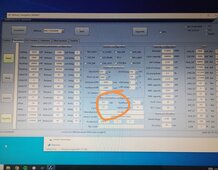
Problem solved! A different value must be entered here where "Current mR" is circled in orange. The default is 2.5. I had to enter 0.1. The BMS then displayed the current. I also had to set the current to 0 when the battery was full and no current was drawn from the battery. Calibrate. Now the BMS displays very accurate current values.
 

Attachments

  • Screenshot_20240510_153658.jpg
    Screenshot_20240510_153658.jpg
    577.2 KB · Views: 11
Sounds a bit like the seplos boards. Buggy.
I don't think they do anything to each other. Real Chinese philosophy. Good products and also a very bad service and support. Before JBD I had Daly🙄. With a lot of patience I managed with Victron. But it worked more badly than right. There was no help from the manufacturer. That's why I switched to JBD. It works better but the description is just as bad.
 
Back
Top