You are using an out of date browser. It may not display this or other websites correctly.
You should upgrade or use an alternative browser.
You should upgrade or use an alternative browser.
Best practice for 300kgf ‘fixture’ 280Ah cells
- Thread starter fafrd
- Start date
Marinepower
Solar Enthusiast
- Joined
- Apr 24, 2020
- Messages
- 224
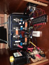
That is a very nice build! I have never seen the "binding barrels" before and it's a great space saver. Wish I had seen this before making my compression solution.
I decided to go with the 'Webber" flexible bus bars however. For a mobile application something flexible seems the way to go.
Here is my messy setup with the Weber busbars. I am also very space constrained.
I also used 1/4 aluminum for the end plates for the compression, but I vinyl wrapped the end plates so they don't become an electrical conductor from one plate to the other via the threaded rods. I also had an aluminum battery tray fabricated (hard to see in image) , so if the electrolyte in the cells ever leaks, it stays contained for disposal.
MP

curiouscarbon
Science Penguin
- Joined
- Jun 29, 2020
- Messages
- 3,017
thank you for posting all this!It seems as though there are an infinite number of ways to build a fixture for a 4s 280ah battery.
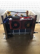
FWIW this is the approach I took...
View attachment 79232
View attachment 79211
View attachment 79212
This battery is for my van camper which I primarily use during the summer to escape the desert heat of southern Arizona. I wanted to be able to easily remove the battery when the van is not in use for the 8 months I spend at my winter home. During the shoulder seasons the temperature in the van regularly exceeds 100 degrees - which is not good for the battery!
Space constraints dictated the design, in particular the overall length. IMHO this design offers some advantages over other approaches. For example: the threaded rod in combination with the binding barrels reduces the overall length and takes some of the guesswork out of 'fixture compression'. The components I used resulted in about the right amount of compression. IE: After the pack is fully assembled you tighten the binding posts all the way, this puts an equal amount of compression on the pack, no need to guess how much torque to apply to the nuts on the threaded rod. If you need more or less compression simply add or remove some washers.
I felt it was important that the threaded rod & binding posts be manufactured with tight tolerances, which I believe these are. It was not necessary to modify the length of the threaded rods. The 8" x 8" aluminum plate works out to be just the right size. So all you need is a hand drill to make the holes in the end plates and a pair of scissors to cut the foam & neoprene separators.
I read somewhere on this thread that Norseal was recommended to use between the cells. The silicone foam I chose had very similar characteristics to what was recommended at about 1/3 the cost. I placed that material between the cells and placed neoprene on the aluminum end plates. The end result is a fairly compact monolithic block that exhibits no lateral flexing or twisting...
View attachment 79213
View attachment 79214
The total cost for this approach is quite high! McMaster Carr sells premium products at a premium price! However - as I said - space constraints forced me to keep the overall length to an absolute minimum. No doubt some of the components could be substituted with something less expensive. I present this BOM as a guide for what to consider when choosing components.

McMaster-Carr
McMaster-Carr is the complete source for your plant with over 595,000 products. 98% of products ordered ship from stock and deliver same or next day.www.mcmaster.com

McMaster-Carr
McMaster-Carr is the complete source for your plant with over 595,000 products. 98% of products ordered ship from stock and deliver same or next day.www.mcmaster.com

McMaster-Carr
McMaster-Carr is the complete source for your plant with over 595,000 products. 98% of products ordered ship from stock and deliver same or next day.www.mcmaster.com

McMaster-Carr
McMaster-Carr is the complete source for your plant with over 595,000 products. 98% of products ordered ship from stock and deliver same or next day.www.mcmaster.com

McMaster-Carr
McMaster-Carr is the complete source for your plant with over 595,000 products. 98% of products ordered ship from stock and deliver same or next day.www.mcmaster.com

McMaster-Carr
McMaster-Carr is the complete source for your plant with over 595,000 products. 98% of products ordered ship from stock and deliver same or next day.www.mcmaster.com

McMaster-Carr
McMaster-Carr is the complete source for your plant with over 595,000 products. 98% of products ordered ship from stock and deliver same or next day.www.mcmaster.com
View attachment 79217
looks awesome!! so minimal and looks robust??
I decided to go with the 'Webber" flexible bus bars however. For a mobile application something flexible seems the way to go.
I agree with you regarding the flexible bus bars. However, my cells came with welded studs. The contact area is very minimal. IE: the studs are 6mm, the contact area is 10mm & the flexible bus bars have an 8mm hole. I tried using washers to help improve the contact area but that introduced a 10 mv voltage drop between each cell. I tried both braided & multi layer copper. I purchased them during my long wait for the cells. That was about a year ago. At that time the only braided or multi layer copper bus bars I could find had 8mm holes. It wasn't until I received my cells that I realized how tiny the contact area was on the welded studs! My 'fixture' should minimize the possibility of the studs moving relative to one another. I'd rather cross that bridge if/when I come to it as opposed to having a 10 mv voltage drop between each cell. NOTE: I measured 10 mv drop between the cells at 30 amp charge/discharge. In this video Ray details how he encountered the same issue, IE: he attempted to use washers to increase the contact area but if anything it made things worse. Thanks for the suggestion regarding the Weber bus bars. Since they have a 6mm hole vs the 8mm hole I may give them a try...
Last edited:
Emporium4579
New Member
- Joined
- Oct 5, 2022
- Messages
- 1
For example: the threaded rod in combination with the binding barrels reduces the overall length and takes some of the guesswork out of 'fixture compression'. The components I used resulted in about the right amount of compression. IE: After the pack is fully assembled you tighten the binding posts all the way, this puts an equal amount of compression on the pack, no need to guess how much torque to apply to the nuts on the threaded rod. If you need more or less compression simply add or remove some washers.
Really nice and clean install and thank you for sharing your materials list.
Follow-up question, I'm confused by your description of the compression effect. After reading 12 pages of calculating spring constants and washer stacks, how did you arrive to this compression approach and how did you calculate how many washers are required? It looks like you're just using lockwashers on both ends?
russellribeiro10@gmail
New Member
Hello guys. I read below to learn this issue of 300kgf to be applied to the cells in order to improve their qty of cycles. This is all fine and I think I understood. I am planning to use two pieces of plywood at each side of 4 3.2V cells and thigh them with 4 rods, two at each side. However I am wonder how to measure these 300kgf when using my wrench toll to tight the nuts of the 4 rods. As far as I understand 300kgf is 2942 Newtons. This is a lot of force. I have a digital Torque toll that an measure up to 300N. So my questions is. How do you guys measure these 300kgf? ThanksI know the subject of the 300kgf ‘fixture’ (compression clamp) to extend cycle life of 280Ah LiFePO4 cells manufactured by EVE from 2500 cycles without fixture to 3500 cycles with fixture has been discussed in various threads on other subjects, but I could not find any single thread dedicated to that subject and now that I have my 280Ah cells and am beginning to think about how to assemble my battery, I am interested in current ‘best practices’ on this subject.
I have run my first charge and discharge cycle without any clamp/fixture and the cells do swell quite a bit.
So if the fixture is calibrated to 300kgf when the cells are empty, force is likely to far exceed that level once the cells are full.
And if the cells are filled before the clamp/fixture is calibrated, already-established swelling is likely to distort the battery far more than if a constant force of 300kgf had been applied during charging.
So my current thinking is to calibrate the clamp/fixture when close to empty (at least not yet bulging) and then to recalibrate every 0.1C or so as the battery charges to full.
There will still be less than 300kgf as the full battery dischargres but when bulging gets most extreme, there should be 300kgf in counter force and overall stability of cell position should be good.
Anyone else who has already faced this issues and solved these problems care to chime in?
My current plan is to use two 1/2” ABS plastic endcaps and two threaded rods per side to create the clamp/fixture.
If anyone has found a good solution to putting an entire 8S 24V 280Ah battery into a stock case with a 300kgf clamping fixture solution, I’m also interested in that..,
Hedges
I See Electromagnetic Fields!
- Joined
- Mar 28, 2020
- Messages
- 21,516
Torque wrench measures newton-meters of torque.
Would think simple geometry would translate that to clamping force, but friction plays a big roll. Look up clamping force vs. torque for a given screw thread, also a function of material.
What some people have done is to use springs, which have a particular force vs. displacement. The spring acts as a scale, and provides compliance as batteries swell with charging, shrink with discharging. (some people put a support under the batteries so they don't fall out when lifted.) Given an anticipated amount of swelling, you can select spring length so pressure remains within desired range.
Not everybody is clamping. And I don't think we've seen any commercial designs with springs for clamping.

 diysolarforum.com
Would think simple geometry would translate that to clamping force, but friction plays a big roll. Look up clamping force vs. torque for a given screw thread, also a function of material.
What some people have done is to use springs, which have a particular force vs. displacement. The spring acts as a scale, and provides compliance as batteries swell with charging, shrink with discharging. (some people put a support under the batteries so they don't fall out when lifted.) Given an anticipated amount of swelling, you can select spring length so pressure remains within desired range.
Not everybody is clamping. And I don't think we've seen any commercial designs with springs for clamping.

Search results for query: compression
Tradewinds63
New Member
- Joined
- Jul 4, 2021
- Messages
- 8
Uhhh. Big time misunderstandings in here about clamping/fixtures and it's purpose... This is an initial few charging cycles degasing procedure for NEW batteries only.
Firstly, I hope none of you applied 300k force to your battery cells.
300kgf in its expressed context by the manufacturer means 300kgf/m2 (something they need to share for the average person). That translates to 0.0003 k per mm² or 0.427 pounds per inch².
Next step is finding the square area of the batteries planar face you intend to clamp and converting the force accordingly. For an LF105 as an example, the compression plane of the battery is 200.5mm X 130.3mm = 26,125.15 mm².
.0003 k X 26,125.15 mm2 = 7.837545 k force or 17.279 pounds applied force.
That's ONLY 17.279 lbs force applied to the the whole series or a single cell. Like having a 17.279 lb cat sitting on something, compressing it, that's all.
If you have different cell amps... You need to find the plane area of your battery and apply the force as provided in the example above.
You also need to know that this force is applied at 30% soc or roughly 3v per cell. AND this fixture state is used for the INITIAL 3 to 5 charging cycles ONLY!
If you didn't do it to your batteries when new... don't bother now, it wont help. If you didn't perform the procedure when new, the gas bubbles will have already caused the damaging seperations between your cells electrodes and their electeolytic compounds and you can't squeeze them back out now. This proceedure is about not providing them the ability to form the early gas seperations to begin with.
To perform the degassing function upon your new cells after you've applied the clamps with the proper force...
The batteries should be fully charge and then discharged to 30% SOC, 3 to 5 times. Once this has been done, the EARLY excess produced gasses will have been purged through the gas valves and the potential gas seperation between the electrodes and the electrolytic compounds is effectively diminished and your cells will be more efficient and provide more cycles than if the degassing function isn't provided.
The clamping fixture is not intended to be permanent and should be removed after this operational procedure phase is complete, this, to allow some minor cooling space between batteries during the banks service life.
I'll do a video later and provide a link here about how to apply this force using a simple scale and jig and using steel strapping clamps with wood ends. It's actually very simple to perform and can be done in many different ways.
Bob B
Emperor Of Solar
- Joined
- Sep 21, 2019
- Messages
- 9,203
@Tradewinds63
Quite some time ago, one of the forum members ..... @ghostwriter66 ....... had a conversation with EVE engineers who verified the specified clamping force. Going from memory, It worked out around 12- 15 PSI ... You'll probably be able to find posts around that conversation with a little searching of the forum ........ Where did you get your information?
Quite some time ago, one of the forum members ..... @ghostwriter66 ....... had a conversation with EVE engineers who verified the specified clamping force. Going from memory, It worked out around 12- 15 PSI ... You'll probably be able to find posts around that conversation with a little searching of the forum ........ Where did you get your information?
Last edited:
Inquiring minds want to know?@Tradewinds63
Quite some time ago, one of the forum members had a conversation with EVE engineers who verified the specified clamping force. It worked out around 15 PSI ... You'll probably be able to find posts around that conversation with a little searching of the forum ........ Where did you get your information?
Bob B
Emperor Of Solar
- Joined
- Sep 21, 2019
- Messages
- 9,203
@Tradewinds63
Quite some time ago, one of the forum members ..... @ghostwriter66 ....... had a conversation with EVE engineers who verified the specified clamping force. Going from memory, It worked out around 12- 15 PSI ... You'll probably be able to find posts around that conversation with a little searching of the forum ........ Where did you get your information?
At that time, some of the EVE spec sheets detailed a gain in cycles if compression was properly applied.
Since that time, there has been a LOT of discussion surrounding compression ...... As a practical matter, it seems that calendar aging may override any difference in longevity gained from compression .... and serious attempts to achieve the specified compression has fallen out of Vogue.
For those of us with LiFePO4 cells in mobile environments, clamping is not optional.
Uhhh. Big time misunderstandings in here about clamping/fixtures and it's purpose... This is an initial few charging cycles degasing procedure for NEW batteries only.
No, cyce life is determined with a fixture. Cycle life without fixture is lower than with fixture in place.
Source: EVE, CATL engineers, my test lab.
Also, see this:
LFP Aries pack in Tesla. Zoom in on the chart in this video (it's very readable in Highest Definition) at this time stamp:
A little further on in the video (16:00 timestamp) you can see the LFP Tesla pack with prismatic cells in their fixture.
LFP Aries pack in Tesla. Zoom in on the chart in this video (it's very readable in Highest Definition) at this time stamp:
A little further on in the video (16:00 timestamp) you can see the LFP Tesla pack with prismatic cells in their fixture.
There was a German video that had a battery engineer on there and he also said what @Tradewinds63 said. That is why the cells are vacuum sealed to try and get all the oxygen(?) out but since they can't get it all out that is what causes it to bloat slightly during the first few full charges. Clamping during that initial few charges is what they claimed increased the cycle count, not the continuous clamping.
Tradewinds63
New Member
- Joined
- Jul 4, 2021
- Messages
- 8
kgf is an informal or casual engineering term and relates to a unit of mass (the kilogram, hence kg. The remainder is f for force. Kilograms force) and should also be accompanied by some other unit of measure such as area, time, etc to provide a specified relationship of work.
Since we are discussing an applied mass force upon a surface area of the battery, the second unit of measure is typically expressed in either mm², cm² or m², etc. If it represented mm², the cells would be crushed if the force applied was equal to 300 kgf/mm² and the cells would also be crushed by 300 kgf/cm². it would be like you standing on a tin can and it buckling under your body wiegth.
300 kgf is the expressed force for the EVE LF line of prismatic batteries and all have far different surface areas, some more than double the smaller LF batteries. But all use the same 300 kgf term without ever expressing the second unit of relational measure. Therefore the reader is forced to engage in some form of rationalized consideration.
The applied force need not be great, these aren't balloons and the gasses will escape through the valve at the top of the battery as they form during the initial charge cycles. Some of the gasses are hydrogen and so forth. It depends on the chemical reaction that's occuring. But all that's needed, is to keep the walls of the batteries flat as possible during the intial charge cycles. Adding too much force can cause the electrolytic compounds to be crushed into thinner layers at the center and becoming thicker about the perimeter of the electrodes, not adding enough force will result in the formation of bubbles within both the region between the electrodes and the electrolytic compounds and the electrolytic compounds themselves. Therefore causing thicker gass infused electrolytic compound layers nearer the center of the electrodes.
You can argue this all you like and swear up and down otherwise but in the end, it is what it is.
This proccedure has nothing to do with restraining batteries in an automobile. This is a wholly seperate matter and is a procedure to degass new lifepo4 prismatic batteries. There's nothing more to it than that. Whether your application is home energy storage, automotive energy storage or you're using these batteries to power your aircraft... Whether you decide to degass them when new or not is up to you and you're free to believe whatever you like, to the contrary or not.
And again, all the EVE manufacturer literature shares the same 300 kgf unit for the entire LF prismatic lineup regardless of amp hrs/size.
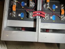
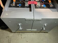
I have built batteries with and without compression. Based on what I’ve seen with my own eyes, most cells do swell in time without fixturing/compression. This usually happens after enough cycles, elevated temperatures + high state of charge. I can also tell you that you can run a bunch of cycles compressed, take it out of compression and one trip to a full charge on a warm day and it’ll likely swell to the point of where I’d be hesitant to fixture it again. Swelling can happen the very first time you top balance, so if you’re going to compress, do it from the beginning. If you absolutely must take cell out of compression to make a change and recompress, do so at a low state of charge and cool cells. If you choose not to fixture, you should allow as much room between the cells as your buss bars can accommodate. My thinking is once you are committed to one method, fixtured or not stick with it. Calendar/chemistry life could be the ultimate tell….in time, we obviously don’t know yet. As for compression, I like 10psi on the wide face. This works out to be about 550 lbs of force on a 280/305 Ah prismatic cell. Anything less, don’t even bother because the cells are just going to push it out of the way WHEN they grow.


My biggest problem with what you are describing is if clamping were only needed ‘during the initial charge cycles’, why wouldn’t that be done by the manufacturer / EVE before shipping (as the final step of manufacturing)?kgf is an informal or casual engineering term and relates to a unit of mass (the kilogram, hence kg. The remainder is f for force. Kilograms force) and should also be accompanied by some other unit of measure such as area, time, etc to provide a specified relationship of work.
Since we are discussing an applied mass force upon a surface area of the battery, the second unit of measure is typically expressed in either mm², cm² or m², etc. If it represented mm², the cells would be crushed if the force applied was equal to 300 kgf/mm² and the cells would also be crushed by 300 kgf/cm². it would be like you standing on a tin can and it buckling under your body wiegth.
300 kgf is the expressed force for the EVE LF line of prismatic batteries and all have far different surface areas, some more than double the smaller LF batteries. But all use the same 300 kgf term without ever expressing the second unit of relational measure. Therefore the reader is forced to engage in some form of rationalized consideration.
The applied force need not be great, these aren't balloons and the gasses will escape through the valve at the top of the battery as they form during the initial charge cycles. Some of the gasses are hydrogen and so forth. It depends on the chemical reaction that's occuring. But all that's needed, is to keep the walls of the batteries flat as possible during the intial charge cycles. Adding too much force can cause the electrolytic compounds to be crushed into thinner layers at the center and becoming thicker about the perimeter of the electrodes, not adding enough force will result in the formation of bubbles within both the region between the electrodes and the electrolytic compounds and the electrolytic compounds themselves. Therefore causing thicker gass infused electrolytic compound layers nearer the center of the electrodes.
You can argue this all you like and swear up and down otherwise but in the end, it is what it is.
This proccedure has nothing to do with restraining batteries in an automobile. This is a wholly seperate matter and is a procedure to degass new lifepo4 prismatic batteries. There's nothing more to it than that. Whether your application is home energy storage, automotive energy storage or you're using these batteries to power your aircraft... Whether you decide to degass them when new or not is up to you and you're free to believe whatever you like, to the contrary or not.
And again, all the EVE manufacturer literature shares the same 300 kgf unit for the entire LF prismatic lineup regardless of amp hrs/size.
It’s a huge PITA for customers and far easier for the manufacturer to take care of it with one set of clamping fixtures rather than having many/most customers take care of it with their own clamping fixtures at incoming quality control (larger commercial customers) or assembly (DIY end-customers). Even if it modesty increases cell cost (I’d happily have paid a bit more for ‘pre-broken-in’ cells that avoided the need to assemble my own clamping fixture).
So I just can’t but what you are saying.
And right or wrong, if you only have one LiFePO battery and go to the trouble of building a 300kgf clamping fixture for it as specified, it’s easier to just leave the battery in the fixture forever (EOL) than to remove the fixture after ‘the initial charge cycles’…
Tradewinds63
New Member
- Joined
- Jul 4, 2021
- Messages
- 8
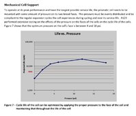
Is the graph you shared something you put together or something someone else did?
I'm currios to know if the test was performed on a single battery or was it performed on a series of batteries?
Next question, how long have you had your compression device in service and have you taken out any cells and tested their capacity to see if they are in line with the Eve cycle graphs for their fixture results? The graphs indicate battery capacity in relation to cycles and should be good enough to compare to after a couple years regular use if used for household power. Obviously there will be calander life effecting the results as well but calander life graphs are available as well.
After looking more closely at the EVE test procedure amongst the several different LF models it would appear they reference the same experiment for all their models and simply alter the compression area dimensions for the specific battery within the literature.
I have built batteries with and without compression. Based on what I’ve seen with my own...
Bob B
Emperor Of Solar
- Joined
- Sep 21, 2019
- Messages
- 9,203
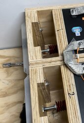
I have seven 4S batteries with EVE LF280N that have been under 640psi for almost three years in a mobile application, they aren’t crushed yet;-)
View attachment 218250
Probably a typo ..... instead of PSI .... Lbs?
S Davis
Solar Addict
- Joined
- Sep 25, 2021
- Messages
- 785
Yes thanks, typo 640lbs total across the face.Probably a typo ..... instead of PSI .... Lbs?
Is that even a serious question here?I have seven 4S batteries with EVE LF280N that have been under 640 pounds of compression
for almost three years in a mobile application, they aren’t crushed yet;-)
View attachment 218250
My 16S 280Ah cells have been in a 300Kgf clamping fixture for over 3 years now with absolutely no signs of crushing…
S Davis
Solar Addict
- Joined
- Sep 25, 2021
- Messages
- 785
I was responding to post 242 talking about crushing the cells.Is that even a serious question here?
My 16S 280Ah cells have been in a 300Kgf clamping fixture for over 3 years now with absolutely no signs of crushing…
Similar threads
- Replies
- 23
- Views
- 2K
- Replies
- 0
- Views
- 428
- Replies
- 38
- Views
- 2K
- Replies
- 8
- Views
- 1K
- Replies
- 15
- Views
- 1K


