diy solar

diy solar

DIY Bus Bar

  • Thread starter Deleted member 1888
  • Start date
D

Deleted member 1888

Guest
Im looking to make my own DIY Bus Bar that can pull 1000amps as buying one is expensive. Im looking to use it to connect a large battery banks. Can this be dune with supplies from hardware stores? Anyone know a good way to make on and what parts to use?

The only one I can buy is this
 
I've bought materials from McMaster-Carr. Here are copper bars:


Here's another vendor:


First thing to do is design your 1000A busbar so it only has to carry 1/2, 1/4 or whatever small fraction of 1000A can be achieved.
How many batteries and how many loads?
If 1:n, at least put the "1" (only battery, or only load) in the middle and distribute the rest. Then 500A goes each direction.
If you bolt through the bar, connecting one cable on top and one on the bottom, it can be half as long.

I have one battery string going to four inverters. The ground bus bar connects those with 3 bolts. Battery to middle hole, two inverters (one top side and one bottom side) to the left hole, two inverters to the right hole.

Similar concept works for mechanical structures. Instead of just supporting ends of a beam, support several points and it can carry far more, also deflects less.
 
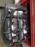
I have 3 batteries right now but I want to add many more in time. So if I can make it with 10 or more bolts that would be good.
 
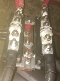
Here's how I hooked mine up.
Battery positive forked with two, 4/0 cable to two fuses. Each of those forked to two inverters.
Inverters have their own breakers so fuses would never blow except for a short.
Battery negative has one 4/0 cable to middle of copper bar. Four cables to inverters come off the bar.
The bar I bought came with standoffs, which I modified to line up with mounting holes on the fuse holders.
Layout and arrangement of batteries minimized all cable lengths.
Not counting cables, it cost about $220, mostly for the class T fuses and holders.


negative bar IMG_0522.jpg
 
it always warms my cockles to see negatives and un-fused positive in such close proximity.

Keep your friends close, and your enemies closer.

I disconnect negative at the battery terminal before wrenching on this cluster.
There is a plastic cover which goes over the fuses.
If you buy the Blue Sea fuse holder, two to choose from. This one had a snap-in clip for the cover, impossible to remove without breaking something. Other model has a latch.

I suppose I could install a sheet of plexiglass under the fuse holders if that would make you feel better for me.
Kind of like how our work areas are separated now.
It would also let me use all four mounting holes per fuse holder, less strain on them than what I have now.
Not a bad idea, really. Thanks for jogging my reasoning abilities.
 
Can you use cables and a stud instead of bus bars? It should be much easier to size that correctly.
 
Can you use cables and a stud instead of bus bars? It should be much easier to size that correctly.
The point is to spread the 1000a load out to many batteries, I can not to that with just cables. Also I don't thing there is a cable that can carry 1000a on the consumer market.
 
If you spread the load, it isnt 1000a.

Here is a 1000a+ setup, but not for sustained throughput.
 

Attachments

  • 20200623_170712.jpg
    20200623_170712.jpg
    178.2 KB · Views: 148
If you spread the load, it isnt 1000a.

Here is a 1000a+ setup, but not for sustained throughput.
That is incorrect the bus bar will still take the full 1000a as will the inverter pulling that 1000a. Only the batteries will not get the full 1000a they share the load. That is why I can just use anything for a bus bar as I do not want the thing to melt or start a fire.
 
How are you hooking up the 1000a inverter? I would assume that's some serious cabling there.

That's why i'm suggesting a stud vs. a busbar. You can connect everything to a central point(the stud) that is sized for the combined load and distribute with cabling according to specific load. Each battery cable is fused and sized for the load of that battery only. You can break out to sub panels that are fused and cabled for the load of that sub panel only. etc.

I don't know about building codes, but I have seen similar systems in emergency vehicles for at least 500a.
 
Take a min to see what 1000a actually looks like. It melts a 3/4" welding rod nicely.


Id like to once again try to dissuade you against attempting this.
 
Take a min to see what 1000a actually looks like. It melts a 3/4" welding rod nicely.


Id like to once again try to dissuade you against attempting this.
The devil is in the details that that units puts out 1000a at 44v = 44000 watts and they don't say what that bar is made of. That generator they are using puts out all of this this is not the same as what im talking about.

Single Phase 120 V: 396 amps (L1-N, L3-N at load)
Single Phase 240 V: 396 amps
Three Phase 208 V: 433 amps
Three Phase 480 V: 198 amps
Prime Power Rating**:Single Phase 120 V: 363 amps (L1-N, L3-N at load)
Single Phase 240 V: 63 amps
Three Phase 208 V: 394 amps
Three Phase 480 V: 180 amps

 
That is incorrect the bus bar will still take the full 1000a as will the inverter pulling that 1000a. Only the batteries will not get the full 1000a they share the load. That is why I can just use anything for a bus bar as I do not want the thing to melt or start a fire.

If the inverter pulls 1000A, that can be done with a busbar carrying only 500A.
If two strings of batteries connect to opposite ends of a busbar, and a (very fat) cable goes from middle of busbar to inverter,
fat cable and inverter gets 1000A
Each battery string delivers 500A
Busbar carries only 500A at any point; that's what its cross-section must handle.

I could use a busbar to join four battery strings (each with a cable, most likely) to two inverter cables, going to one inverter.
Then the battery cables and the busbar would only carry 250A. The inverter cables wold each carry 500A. The inverter gets 1000A.
(could as well have been two busbars, each joining two battery strings to one inverter cable.)

That's what I meant about "designing your busbar"
 
that units puts out 1000a at 44v = 44000 watts and they don't say what that bar is made of.

You continue to reinforce the my belief that your in way over your head. 1000 amps is a 1000amps. This is why the wire size for 10amps of 12v is the same as 10a of 600v. yes the power delivery is different for those two, but that doesn't matter to the current that the wire/connections have to carry.

I'm out guys, I did my best.
 
If the inverter pulls 1000A, that can be done with a busbar carrying only 500A.
If two strings of batteries connect to opposite ends of a busbar, and a (very fat) cable goes from middle of busbar to inverter,
fat cable and inverter gets 1000A
Each battery string delivers 500A
Busbar carries only 500A at any point; that's what its cross-section must handle.

I could use a busbar to join four battery strings (each with a cable, most likely) to two inverter cables, going to one inverter.
Then the battery cables and the busbar would only carry 250A. The inverter cables wold each carry 500A. The inverter gets 1000A.
(could as well have been two busbars, each joining two battery strings to one inverter cable.)

That's what I meant about "designing your busbar"
I can do it with a 500a bar? what awg cable would I need to do this safly?
 
You continue to reinforce the my belief that your in way over your head. 1000 amps is a 1000amps. This is why the wire size for 10amps of 12v is the same as 10a of 600v. yes the power delivery is different for those two, but that doesn't matter to the current that the wire/connections have to carry.

I'm out guys, I did my best.
 
The devil is in the details that that units puts out 1000a at 44v = 44000 watts and they don't say what that bar is made of. That generator they are using puts out all of this this is not the same as what im talking about.

Single Phase 120 V: 396 amps (L1-N, L3-N at load)
Single Phase 240 V: 396 amps
Three Phase 208 V: 433 amps
Three Phase 480 V: 198 amps
Prime Power Rating**:Single Phase 120 V: 363 amps (L1-N, L3-N at load)
Single Phase 240 V: 63 amps
Three Phase 208 V: 394 amps
Three Phase 480 V: 180 amps


Yes, and it isn't the 1000A through the welding rod that melts it (but that might happen eventually)
It is the 44 kW being dissipated in the plasma which melts the rod.

If the 3/4" rod was copper not steel, it would carry 1000A all day. Maybe about 80 degree C rise above ambient, I'd have to compare cross section with wire gauge ampacity charts to estimate better.

If the rod sticks to the workpiece (as happens a lot to me), the rod gets warm but so does the 180' of copper cable I use, and the transformer. Power dissipation is spread thin, and nothing melts quickly.
It is that old problem about what impedance of load maximizes power transfer. Goal here is to put most of the power into the arc (so it melts tip of rod and contact point of workpiece), not the wires or the full length of the rod.
 
Last edited:
I can do it with a 500a bar? what awg cable would I need to do this safly?

Yes, or possibly 250A bar.
Sketch out the geometrical configuration you want: load, battery strings, cables, busbar.
I'll see what I can figure out from that.

I've done PCB and IC layout as well, where we try to match voltage drops and avoid overloading conductors. Some things balance themselves, some go into runaway.
 
Back
Top