diy solar

diy solar

Cell voltages different when compared with screw terminals? (i.e screw vs busbar)

9xsolar

New Member
Joined
Jun 21, 2020
Messages
5
I'm finally in the process of building my first LifePo4 pack and I bumped into a really weird behavior that I can't quite explain.

If I compare voltages between screw terminals, I get reading A.
If I compare voltages between busbars (connected to the same screw terminal), I get a different reading B.

The difference is more than 0.1v (i.e 3.2v vs 3.34v)

I first noticed this in my BMS testing when it was reporting higher voltages than my voltage readings which I was doing against the screw terminals directly. Any idea why and is this normal?
 
The bolts are stainless, and will show a lower voltage than the bussbars.
If you are reading lower at the bussbars, there is a connection, or oxidation issue present.
 
Now try reading voltage directly between a screw and the busbar. If accessible, battery terminal to busbar, battery terminal to screw. On lower DMM scale this will provide more significant digits. The first four counts of a DMM/ADC are too few to be relied upon. Reverse meter leads and read again, so you can see if DMM has offset.

When there is current flow, IR drop will show up across contacts, greater drop for poor contact. Also across a length of wire or busbar.

Even with no current flow there can be voltage across a contact between dissimilar metals, especially in the case of heat flowing through them. Normally that's more of an issue at the microvolt level.

People have been reporting resistive contacts to lithium batteries. It appears they are bare aluminum, which will develop non-conductive oxide, so they need to be cleaned and sealed in some manner. As for the busbars, that will depend on whether they are tinned or not.
 
I'm reading higher voltage at the busbar when there's active power flowing (i.e 5A charging). 3.25v at the stainless screw/bolt while it's 3.38v (or higher) when touching the copper busbar. Usually its higher in the busbar than the other way around.

No idea if the busbars are tinned, so higher at the copper busbar is normal? ?
 
Last edited:
Sounds like current through busbar to battery terminal has 130 mV drop (for two interfaces?), while the screw is making good contact to terminal and not to busbar. About 3% of energy being lost in the interface, and voltage error will be seen by BMS.

Check all cells the same way, see if some have more contact resistance than others.

But try measuring busbar to screw, or if accessible battery terminal to busbar, so cell voltage not included. This lets you compare contact resistance directly and not cells.

So this is at just 5A. Guess what happens when you discharge at 50A? That drop should increase to 1.3V per 3.25V cell, losing over 1/3 of your power and making busbars uncomfortably hot (unless BMS objects first).

Tinned aluminum will have a shiny finish, just like tinplate steel. Aluminum can have a flatter more grey finish, or more likely will be electro-polished to a mirror finish but then starts oxidizing. Beyond that there are electrochemical methods (look up potential of various materials, make a battery out of two pieces of metal stuck in a lemon and measure potential difference. Iterate until your "unknown" is narrowed down sufficiently.)

Check other threads here for peoples' experience cleaning lithium battery terminals and applying corrosion inhibitor. For one guy it made a world of difference.
I see it opposite.
Since the screw is lower voltage, the bussbar is making good contact, but the steel screw is resistance dropping the voltage.
No?
 
"(i.e 5A charging). 3.25v at the stainless screw/bolt while it's 3.38v (or higher) when touching the copper busbar."

I took this to mean charging current is applied to the busbar (far end of busbar, where it is screwed to another cell) and 3.38V is found between busbar negative and busbar positive. No way screw can be at higher potential than the busbar if current is fed through the busbar.

Now how could screw be lower than busbar?
OK, if busbar has no contact what so ever with cell and poor contact with screw, then current could flow through screw and have voltage drop.
Alternatively, what I was thinking, was busbar made some contact with cell but had voltage drop. If screw had good contact with busbar it would be same voltage. It's voltage is lower, so poor contact with busbar. Screw has either equally poor contact with cell, or good contact with cell. So screw voltage is either same as cell or between cell and busbar.

Not sure his exact location of contact on each side of cell, though.
 
Could you post a picture of your pack .... and indicate where you are checking the voltages if possible.
 
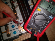
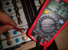
Here's a test during discharge (10amp controlled discharge). My pack is 2p16s (total 200ah) built from 32 100ah cells. All cells are compressed using 4 threaded rods for each group (can see below).

On the screw itself :

screw.png

On the busbar :
Busbar.png


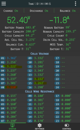
Here's what the BMS reports (I'm using 0.6amp active balancer with bms option) - the cell group pictured above is number 8.
Capture.PNG


I tried to charge these groups in particular separately but even if they touch 3.62+, they immediately come down to 3.2/3.3 unlike the other cells. The voltage on the screw is always higher and consistent than the busbar while discharge while completely opposite during charging. What am I doing wrong? :(
 
Clearly IR drop.

I'm still guessing the screw makes a tap to the battery terminal and lets you see its voltage. Can you probe the battery terminal itself?
Try measuring from battery terminal to busbar. Something like 0.35V (or 0.17V if your measurement spanned two, screw to screw vs. busbar to busbar)

Are all batteries consistent in this reading? Another guy had only one or two that behaved this way.
You've got non-plated bare copper busbars.
Try scrubbing oxide off aluminum terminals, applying corrosion inhibitor, re-torquing screws. That fixed the other guy's problem.

Nothing between busbar and battery terminal, such as a stainless steel washer, correct? don't want any poor conductor in the path.
 
Back
Top