I think that cell needs a hydraulic press.Just put a clamp on it hehe it'll be ok... (just joking)


You are using an out of date browser. It may not display this or other websites correctly.
You should upgrade or use an alternative browser.
You should upgrade or use an alternative browser.
battery ballooned
- Thread starter jvbutter01
- Start date

Marinepower
Solar Enthusiast
- Joined
- Apr 24, 2020
- Messages
- 224
I have some EVE 280 cells on route and have been researching top balance methods for when they arrive.
"Marine How To's" (Rod Collins) seems to me to be the most intuitive way to top balance.
See: https://marinehowto.com/lifepo4-batteries-on-boats/. Warning - very long - you will have to scroll through a lot of info to get to the cell balance section.
In summary,: parallel charge to 3.4v until near zero amps, then repeat to 3.5v and then 3.6v. Use a biggish power-supply for large banks if possible to reduce time in the knees.
He also has good advice on how to calibrate your bench top power supply (echoing many comments on this thread). Note that his balance method is designed for Winstons or CALB, so for these EVE cells I think a slightly reduced voltage may be appropriate.
I have some EVE 280 cells on route and have been researching top balance methods for when they arrive.
"Marine How To's" (Rod Collins) seems to me to be the most intuitive way to top balance.
See: https://marinehowto.com/lifepo4-batteries-on-boats/. Warning - very long - you will have to scroll through a lot of info to get to the cell balance section.
In summary,: parallel charge to 3.4v until near zero amps, then repeat to 3.5v and then 3.6v. Use a biggish power-supply for large banks if possible to reduce time in the knees.
He also has good advice on how to calibrate your bench top power supply (echoing many comments on this thread). Note that his balance method is designed for Winstons or CALB, so for these EVE cells I think a slightly reduced voltage may be appropriate.
I think the method described in that article is the best option. Reasonably simple, Reasonably Safe
The Marinehowto "Parellel Step Method" of top balancing
Code:
Parallel Step-Method Top Balance:

1- Wire the cells in parallel
2- Set the power supply to 3.400V and 80% or less of the rated amperage (80% to not burn it out)
3- Turn on power supply and charge cells to 3.400V
4- When current has dropped to 0.0A at 3.400V turn off the power supply & set it to 3.500V
5- Turn on power supply and charge cells to 3.500V
6- When current has dropped to 0.0A at 3.500V turn off the power supply & set to 3.600V
7- Allow current to drop to 0.0A (or very close) at 3.60V
8- Done, pack is balanced.

WARNING: Top each cell up, to a similar SoC level, prior to wiring them in parallel.
Nordkyn Design Recommends a Similar Method:
If possible at all, use a PSU that is explicitly suitable to charge a battery; in doubt, use great caution as a mishap can easily damage it. If smoke escapes from it, you will never get it back in.
- With the output disconnected, set the voltage regulation limit at 3.40-3.45V and preset the current limit (if any) to a value that won’t overload the PSU. Refer to the manual as required. In doubt, always start with a low current limit and never exceed 80% of the rated output.
- With all the cells wired in parallel, connect the PSU, bulk charge and absorb until no current flows any more. The voltage will stay around 3.3V for a very long time before starting to rise. Charging this way can take several days. This will near-fully charge the cells without stressing them unduly, but don’t hold them at that voltage indefinitely. Keep checking up on them at least a couple of times each day. Briefly disconnect the cells and recheck the voltage limit setting on the PSU: better safe than sorry. Avoid charging the cells individually, or in batches; the whole process would take just as long, but would also result in some fully charged cells lying around for several days.
- Once the voltage has reached the PSU output regulation limit and there is no apparent charging current any more, disconnect the cells from the PSU and increase the output voltage regulation limit to 3.60V.
- Then, while standing by only, reconnect the cells and allow the voltage to rise up to 3.60V and stabilise for a few minutes; this normally takes little time and additional current, provided the cells were fully absorbed at the lower voltage. Whether you target 3.60V, 3.65V or even 3.70V is of no consequence or interest if you are actively monitoring the process, because these values are often reached seconds apart only.
- Disconnect the PSU from the cells again and wait. The cells should hold above 3.50V for at least 30 minutes. If not, bring them up again and hold them for a little longer until they do. At 3.60V, you may need to insist a little more than if using 3.65 or 3.70 volts; that’s all.
I recommend reading the articles in their entirety or at least the sections pertaining to balancing. They include more context and guidance than the bullet points above.
Last edited:
Marinepower
Solar Enthusiast
- Joined
- Apr 24, 2020
- Messages
- 224
Thxs for posting.
That Nordkyn Design description of the process is a clearer and more user friendly than the post I linked.
That Nordkyn Design description of the process is a clearer and more user friendly than the post I linked.
I wanted to do it that way but it was taking too long. If I had a charger with more amps it would have been fine.In summary,: parallel charge to 3.4v until near zero amps, then repeat to 3.5v and then 3.6v. Use a biggish power-supply for large banks if possible to reduce time in the knees.
When charging to 3.65 volts, once the voltage gets to 3.4 volts the voltage starts to rise quickly anyways so not much time is spent in the upper knee. Using a 12 amp charger it took my cells apx. 4 hours to get from 3.4 volts to 3.65 volts. That's quick compared to the 5 days total it took to get there.
I do like the point that's been made of setting the power supply's voltage before connecting to the cells. That is a very important point to follow. If that step is followed there is little chance of overcharging cells. But the cells should still be monitored closely once 3.4 volts is reached.
I like the way it's explained much better. Especially the photos of the cell levels.That Nordkyn Design description of the process is a clearer and more user friendly than the post I linked.
Marinepower
Solar Enthusiast
- Joined
- Apr 24, 2020
- Messages
- 224
Something I learned by reading the Nordkyn Design description of top balancing (in its comments section) is that when you are top balancing at a high / medium current and low voltage like 3.5 volts on big pack , you need really beefy and short cables or you will have excessive voltage drop and extend your charging time.
Makes sense, small voltage means more resistance.
The crapy cables that come packaged with cheap bench top power supplies will not cut it. Nor alligator clips for connections I would think for the same reason.
Makes sense, small voltage means more resistance.
The crapy cables that come packaged with cheap bench top power supplies will not cut it. Nor alligator clips for connections I would think for the same reason.
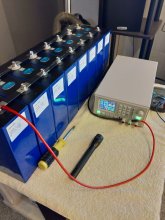
That's very true. I used 12 AWG wires, each 2 feet long, and had a .2 to .3 voltage drop. There will always be some voltage drop no matter how big the cable is. I was using a charger and the current sustained going into the cells was 12 amps. I had the voltage set at 3.65 volts. Once the display on the charger hit 3.60 volts it switched from constant current to constant voltage mode. It should have not done that until it reached 3.65 volts. The voltage right at the cell terminals was 3.391 volts. But the charger still went into absorb mode and the current started to drop.
When the chargers display showed 3.65 volts, the voltage at the cell terminals was 3.65 volts. And when the current had dropped to 90ma's, the charger shut off. Charging these big cells at low voltages can be challenging and requires a lot of patience. I am glad that part is finished.
When the chargers display showed 3.65 volts, the voltage at the cell terminals was 3.65 volts. And when the current had dropped to 90ma's, the charger shut off. Charging these big cells at low voltages can be challenging and requires a lot of patience. I am glad that part is finished.
Attachments
Good point, hadn't considered this and haven't seen that mentioned before. There is often gold hiding in the comments section.Something I learned by reading the Nordkyn Design description of top balancing (in its comments section) is that when you are top balancing at a high / medium current and low voltage like 3.5 volts on big pack , you need really beefy and short cables or you will have excessive voltage drop and extend your charging time.
Makes sense, small voltage means more resistance.
The crapy cables that come packaged with cheap bench top power supplies will not cut it. Nor alligator clips for connections I would think for the same reason.
Looking at the online wire calculator I believe 6 AWG was recommended...lol. However others have recommended 10 AWG. I ordered my 12 AWG wire off of Amazon. Some of the reviewers, or maybe it was answered in the questions section, thought the wire is closer to 11 AWG. I thought about doubling it up but since I had the full 12 amps going into the cells I decided not to.Good point, hadn't considered this and haven't seen that mentioned before. There is often gold hiding in the comments section.
I do plan to charge my pack after I have drained it with the Riden. I know it will take at least 24 hours. I don't know how long the absorb time will take.
Solarfun4jim
Solar seduced :-)
No mention on Will Prowse top balance video, of using thicker leads than those supplied with the PSU. If this is such an important factor, perhaps it should be highlighted, since it is being watched by thousands that think 'you cant screw it up' (comment at 4.26 in the video), means they are good to go.
Ps not having a go at Will's video, by the way, but if something needs a bit of clarification, it is worth putting out there.
Ps not having a go at Will's video, by the way, but if something needs a bit of clarification, it is worth putting out there.
Last edited:
Marinepower
Solar Enthusiast
- Joined
- Apr 24, 2020
- Messages
- 224
My view is that beefy cables for top-balance is both a critical and not so critical consideration.
When the currents are high (above 3 amps) the voltage drop is going to be significant in relation to the charge profile of LFP. Even a 0.05 volt drop makes a big difference extending the charge time required by a lot. But as the cells absorb and the amps drop down to very low current levels the impact will be much smaller. So small cables should still work but it will just take longer.
For me, I plan on a very short run of 10 gauge with appropriate ring terminals at both ends and solider as opposed to crimped connections. The contact surface on the power-supply terminals on my cheap Amazon power supply are so small, i'm not sure there is much point going much larger a gauge of wire. But this is just a guess. I would be interested in an electrical engineer's view.
Sillyputty
Solar Enthusiast
- Joined
- Jul 21, 2020
- Messages
- 188
WARNING: Top each cell up, to a similar SoC level, prior to wiring them in parallel.
Why oh why isn't this stated first? Not that I've ever followed directions as written - but someone might... ¯\_(ツ)_/¯

I noticed that. I don't understand the reasoning behind it and perhaps someone else can explain it. But it could be concern of high current going between cells of different voltages when connected. Since most of the cells we get have voltages very equal to each other this is not a concern.Why oh why isn't this stated first? Not that I've ever followed directions as written - but someone might... ¯\_(ツ)_/¯
I would be interested too.I would be interested in an electrical engineer's view.
I failed to mention my Riden came with fork connectors and I soldered them to the wires and soldered the wires to ring terminals on the other end. I am sure this made a big improvement as opposed to using banana plugs on the power supply and alligator clips on the cells.
I would be interested too.
I failed to mention my Riden came with fork connectors and I soldered them to the wires and soldered the wires to ring terminals on the other end. I am sure this made a big improvement as opposed to using banana plugs on the power supply and alligator clips on the cells.
Most nanner plugs suck.
ghostwriter66
"Here - Hold my Beer"
Why oh why isn't this stated first? Not that I've ever followed directions as written - but someone might... ¯\_(ツ)_/¯
View attachment 26861
SO we use to TOP balance allot of cells -- now days the Chinese have got really good at sensding all the cells from a siongle batch at one time so most of the cells are all equal voltage when you get them (yes I have become lazy)
With that said -- the step method listed above is the proper EE school way of balancing these batteries and thats how I balance my own batteries ...
However I do not waste time getting all the batteries up to the same level to then top balance .. i have often thrown in a battery that is 2.6 while others were 3.1(+/-) and paralleled balanced and they have all been fine in the end ... also using short thick cables is 100% correct - otherwise you do get some voltage loss (but not as much to be concerned about)
But why? Is it out of caution or does it improve the top balance?With that said -- the step method listed above is the proper EE school way of balancing these batteries and thats how I balance my own batteries ...
Sillyputty
Solar Enthusiast
- Joined
- Jul 21, 2020
- Messages
- 188
SO we use to TOP balance allot of cells -- now days the Chinese have got really good at sensding all the cells from a siongle batch at one time so most of the cells are all equal voltage when you get them (yes I have become lazy)
With that said -- the step method listed above is the proper EE school way of balancing these batteries and thats how I balance my own batteries ...
However I do not waste time getting all the batteries up to the same level to then top balance .. i have often thrown in a battery that is 2.6 while others were 3.1(+/-) and paralleled balanced and they have all been fine in the end ... also using short thick cables is 100% correct - otherwise you do get some voltage loss (but not as much to be concerned about)
Thanks - although I'm confused a bit (not unusual):
You seem to say that "the step method listed above is the proper EE school way of balancing these batteries and thats how I balance my own batteries..." but then go on to say:
"I do not waste time getting all the batteries up to the same level to then top balance..." which eliminates one of the (not numbered) steps.
The 'complete' list now is:
1- Wire the cells in parallel
2- Set the power supply to 3.400V and 80% or less of the rated amperage (80% to not burn it out)
3- Turn on power supply and charge cells to 3.400V
4- When current has dropped to 0.0A at 3.400V turn off the power supply & set it to 3.500V
5- Turn on power supply and charge cells to 3.500V
6- When current has dropped to 0.0A at 3.500V turn off the power supply & set to 3.600V
7- Allow current to drop to 0.0A (or very close) at 3.60V
8- Done, pack is balanced.
In other words - top balance the battery pack - not the individual cells.
Similar threads
- Replies
- 9
- Views
- 430
- Replies
- 32
- Views
- 2K
- Replies
- 11
- Views
- 522