diy solar

diy solar

Heltec BMS' (up to 350A) with Active Balancing & Independent Active Balancers

Hey, we are speaking about an active balancer, not about the low cell disconnection!
The 2,1V limit is the voltage below which the load balancer will stop to try equalizing.
Your SCC/BMS is in charge of avoiding a deep discharge, not the balancer.
All kinds of stuff has been discussed in this thread. Its sorta become a catchall for Heltec conversation, and heltec makes Active Balancers, Active Balancing BMSes, Passive Balancing BMSes, Smart BMSes, Dumb BMSes. From what I recall Joey was referring to the hardcoded LVD of one of the dumb BMSes. Its a little hard to keep track of who is talking about what and when :)
 
After ordering my cells (52 Lishen 272AH for 2 sets of 24 cells, with 4 spare), and a Heltec smart BMS 200A model for me to fiddle with, I've had cold feet on my plan to use this in my 'live' 2 installs. Reading more discussions of Mosfet vrs SSR vrs Relays for switching high currents etc and my plan to have 3 strings of 8 cells each with BMS in parallel. Addition complication is that I have to get this installed remote in France while I'm in Australia, and I'd like to monitor it remotely over the year as well. Additional concerns that have weighed on me are the speed of Heltec design changes (3 models proposed in 30mins !) confusion about who exactly makes them, reliance on only a Chinese smartphone bluetooth app (that needs 3rd party APK support) (no option it seems for a PC to set parameters and monitor), chaotic website lack and Aliexpress store, lack of accessible decent documentation and stated 'unsupported' using 3 BMS for 3 strings in parallel (but I cant see how they would even know). The potential for one string to disconnect and put additional load/charging to the remaining also raises the costs as I need to scale each for that.

I'm now leaning to running my cells as 8 sets in series of 3 in parallel with one BMS, and using an Electrodacus. It does not attempt to pass the current etc, but relies on signally a charger and/or load switch as needed. In my case Victron Qattro and a Smart Solar MPPT. I'll add a battery protect for minor DC loads as well to enable them to be disconnected by the BMS if needed. I like Electrodacus doco and design goals (but wont use their Solar panel aspects). It has wifi too, and now supports being a client on my boat's Wifi Access Point, so I can connect with a PC, and remotely control that to enable parameter setting and long term monitoring. I have a basic Surface pro 2 Win10 machine I can dedicate for this task, as well as being a 'user accessible' display. Since I'm only using one SBSM0 vrs 3 Heltec or other BMS, overall complexity is reduced and costs lower too.

I'm more comfortable with running 3 cells in parallel now, as loss of individual cell visibility is less of a concern given how 3 in parallel behave. Even if one cell is grossly mismatched in capacity, the 3 behave in a self levelling way with the weak cell getting carried by stronger cells. (unlike the case when in series). Initial top balance will be important to match the SoC of 8 sets of 3 cells as close as possible . I will run a 'dumb' active balancer as well to try to help the sets remain in balance enough to not degrade the pack.

I've ordered some tiny 6AH LiFePO4 to play with and will get a spare Electrodacus for here to test. I'll check out the Heltec too now that I ordered it and hope I can on sell for a more suitable application. I will report anything useful I learn from that.
 
Last edited:
@dRdoS7

If you want to play with RS-485, check the document attached. It's written with the balancer in mind, but should work identically for the BMS. Once I get to it, I can add support for this also for the monitoring software from @BarkingSpider (https://github.com/BarkinSpider/SolarShed/).

Would anyone be interested in stand-alone PC software?
 

Attachments

  • RS485.pdf
    1.8 MB · Views: 15
Hi,

@dRdoS7

If you want to play with RS-485, check the document attached. It's written with the balancer in mind, but should work identically for the BMS. Once I get to it, I can add support for this also for the monitoring software from @BarkingSpider (https://github.com/BarkinSpider/SolarShed/).

Would anyone be interested in stand-alone PC software?
I'd be interested. I was using Teamviewer to see the phone in the garage, but it was dropping out, and sometimes hard to re-connect. That worked over WiFi. Then I found SCRCPY, which uses USB to a PC, it also drops out a bit, but easy to re-connect. Running software direct connected to the PC (no phone/BT required) would (hopefully) be much better.

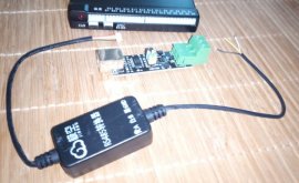
This is what I have for RS485 > USB:

BMS-RS485-USB.jpg

I haven't looked for connection info to wire up to the USB adaptor yet. It's possible that don't need the USB adaptor, and I can connect direct to a USB plug.

Thanks,

dRdoS7
 
I started charging with 50A and my delta has been staying around .03V.
So, now the active balance is on all the time.
I thought that might happen.
I am guessing the IR has more effect when using higher amps.

I will have this all figured out someday.
 
If you can reduce the current, charge or discharge, and watch the cell voltages. See if they are steady or are some bouncing around. My 48 to 12 volt DC-DC converter makes a few of my cell voltages go goofy. Since I do not need that running for now, I have not taken too much time diagnosing how the noise is getting into the BMS. But the instant I turn off that DC-DC converter, my cell voltage settles and they are within 0.005 all the time now. Even during high currents, I rarely see the cells diverge more than 0.010 volt.

How do you have the balance leads connected to the cells? Ideally, they should be equal resistance between cells. On my pack, there were already tap points at the middle of each buss bar. That seems to work great. On the larger cells with bolts, you can connect to one cell end of the buss bar, but then you should connect all of the balance leads the same way. For example, all on the negative terminal of a cell. This way each pair of balance leads has one cell and one buss bar between them. The only one that will differ would be the top cell as there most likely is no buss bar off of the last cell to include. If you do see that one show off balance under high current, you could use one more matching bus bar between the top cell and your load/charge cable, and include that bus bar in the top balance lead. If you have both balance leads on one cell, and the next cell has the balance leads outside of both a plus and minus side bus bar, then you will see the voltage differ based on current flow. At 100 amps, even a tiny resistance will show a voltage drop.
 
I have all of the balance leads on the positive terminals except the black one.
Wire resistance varies from .128 - .164

I turned current down to 10A and the delta went down to .005 and balancing stopped.
I turned current up to 20A and the delta went up to .01V and balancing started again.

I might need to start swapping cells to match IR better.
 
Hi,

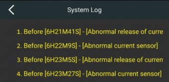
Has anybody else seen this message on the JK App?


Current Error.jpg

It came up twice in succession this morning.

I have seen it a few other times, just before, but not always, when a cell reaches the High setting.

I checked my Midnite Classic log, and didn't see any sudden change in Amps that might have caused this error. There was no high current in or out of the bank.

Thanks (and Happy New Year),

dRdoS7
 
Hi,

Has anybody else seen this message on the JK App?


View attachment 31917

It came up twice in succession this morning.

I have seen it a few other times, just before, but not always, when a cell reaches the High setting.

I checked my Midnite Classic log, and didn't see any sudden change in Amps that might have caused this error. There was no high current in or out of the bank.

Thanks (and Happy New Year),

dRdoS7
I haven't seen that. Did that log come up on it's own or did you find that somewhere? I would like to see a log.
 
Hi,

I only noticed the Log after updating to a later version of the app. Pressed the 3 dots top RH corner to check the version number, saw "System Log".

I was probably better off not knowing. Now I worry its current sensor is going to fail!

dRdoS7
 
Hi,

I only noticed the Log after updating to a later version of the app. Pressed the 3 dots top RH corner to check the version number, saw "System Log".

I was probably better off not knowing. Now I worry its current sensor is going to fail!

dRdoS7
I want that log. I will see if there is an update available for me.
Hopefully those messages don't mean that you have a hardware problem.
I don't know where you got your BMS but you might be able to ask for tech support.
They might tell you what the messages mean.

I had set my Amp limits low and hit the charge and discharge limits.
I'm glad I noticed right away because it was cutting off and turning back on.
It wasn't smooth and made my lights flicker.

It's probably not good to let that happen over and over.

And without a log stuff like that could happen but if you aren't paying attention you might never know.

Over and under voltage limits can trigger and recover. But we need to know about it
 
Hi,

I want that log. I will see if there is an update available for me.

There are some links a few pages back.

And without a log stuff like that could happen but if you aren't paying attention you might never know.

Hardly a day goes by that I'm not checking mine.

Eventually, when I trust the BMS & Batteries, I'll relax.

Maybe.

ATM, all seems to be working OK.

dRdoS7
 
Last edited:
I pulled up the log on mine. Hmmm.
I do not see any current errors, but it does show
[APP open charge]
[APP open discharge]
[APP close charge]
[APP close discharge]
many times. and a few
[Boot] messages.
The odd thing is, these are happening while the Schneider inverter is charging and it is not seeing any error of the battery going open. The time stamps of the open and close events are sometime in the same second or just 1 second apart. And it says APP which I assume means the phone app is issuing the command? I don't know. 16 log entries in just 4 minutes. Looking at the data on the XW, no errors at all, Charging at 1KW and almost 2 KW powering the house from solar. Battery voltage on a very steady climb, from 51.8 volts at 9 am up to 54 volts at 11:30 am. Charge current is near dead flat, with just one little glitch where the current dipped a quarter amp shortly after 11 am. Is that when I connected to the BMS? Looks close. The BMS time is just time since powered up, not real time. And it just did another 0.6 amp dip just now, and I am not connected to the BMS. It does look like the dips may be happening when a cloud passes over as I see a slight dip in the 15 minute sample from Enphase as well.
 
I downloaded the JK app from the Play Store but the 1234 password won't let me pair.
The app is called ENJPOWER
I see JK updates the app often.
Heltec still has the same version I origanally got.
 
In my opinion it's great. It has tons of configuration options (like charge an discharge over current protection, low temp cut-off that is configurable and works, over and under voltages etc.), robust enclosure without any dongles dangling about (on the later models they make, the ones encased in black aluminium). They can also actually handle the advertised current and have a pretty high charge current compared to others. Once I had them configured, they just sit there doing their job and I haven't had to think about them since. I introduce test failures at times to see if they (and the rest of the system) operate as they should, and no issues thus far.
I have the same BMS and i am looking for the instruction manual. Were you abel to get the manual from Heltec?
 
Try 123456 for the advanced password. For the BT password, I think blank works, or 1111. I have not had to re pair mine in months.
 
I got in. I forgot l had changed the password. lol
Like you said, the log should have the date and time instead of the days, hours, minutes, seconds since I turned the BMS on.
 
Back
Top