martin.triska
New Member
- Joined
- Jun 27, 2021
- Messages
- 8
Should I apply larger load directly on the battery (bypassing the BMS)? I'm unable to apply load through the BMS since the voltage just drops way down.


Thru the BMS if possible, you are looking for low cell voltage. If the BMS shuts down, then you have to check each cell with the voltmeter under load.Should I apply larger load directly on the battery (bypassing the BMS)? I'm unable to apply load through the BMS since the voltage just drops way down.
Well, the thing is that the voltage is cut off even without load. Through the BMS I get only 10.8V with no load, whenever load is applied, the voltage drops to a value when the load shuts down. During the whole thing, the individual cells measure 3.34V (both using multimeter and in the app). And since app is showing correct voltages for each cell, it seems that the balance leads also shouldn't be the culprit right?Thru the BMS if possible, you are looking for low cell voltage. If the BMS shuts down, then you have to check each cell with the voltmeter under load.
Are you certain you don't have a cell connection that doesn't have excessive resistance and balance leads also have a good connection? The BMS is looking for 2 things under load, individual cell voltage that hits the low voltage cutoff setting and the other is full pack voltage. Either one can cause a cutoff.
If you can connect with BT and the voltage still drops, then I would say the BMS internally has failed.Well, the thing is that the voltage is cut off even without load. Through the BMS I get only 10.8V with no load, whenever load is applied, the voltage drops to a value when the load shuts down. During the whole thing, the individual cells measure 3.34V (both using multimeter and in the app). And since app is showing correct voltages for each cell, it seems that the balance leads also shouldn't be the culprit right?
Also, I tried applying load directly to the battery + and - and it works fine, no cell drops in voltage.
It sounds like it has failed to me as well.If you can connect with BT and the voltage still drops, then I would say the BMS internally has failed.
I prefer a derate of 50% on any Chinese BMS, with a 60a Daly, I would limit load to 30a.
Daly likes to change things at random, especially on their 4 cell models. Your guess is as good as mine about where (or even if) the key pins are now.Hmm, but how do I load it if the voltage just drops? Invertor won't run on 7V (and I suspect that it didn't drop further just because the LEDs stop drawing any current at that voltage.)
Also do I understand it correctly that if I'm able to connect to BMS via bluetooth, it is already waken up? To me feels like the BMS is actually cutting off discharge for some reason I didn't find yet... After switching off and on the "discharge switch" in app, it briefly gives me the 13.4V, but then it re-evaluates something and shuts the discharge off.. At least that is the feeling I get.
I'm also attaching picture showing which 2 pins I tried shorting - just in case I didn't guess the correct 2 pins:
you could but thats a lot of monitoring to avoid damage. the best thing is to get the battery monitor dongle with the on/off switch. its like 10 bucks on amazon and it fixed all the issues I had with my DALY.Hey, one more sinister idea: if I can't get my hands on another BMS before I leave for vacation, can I just do following?
Connect BMS but use it only for charging and connect load directly to battery +. I would regularly (daily) check the battery voltage and manually disconnect if voltage gets close to 12V (or any cell drops below 3V). Additionally the solar charge controller will have setting to stop charging at given voltage.
My use case: I intent to run only small loads - small 12v fridge, some LED lights and charge laptop/phones from it. I don't expect to ever draw more than 15A. For this purpose I have over-sized system with 280ah battery.
Am I crazy for thinking about doing it this way?
It does sound as if the lack of precharge when connecting the inverter fried it, since you didn't have the balance leads connected (that supply power to the BMS).Update on my 16s DALY BMS. after useing the BMS and batteries for about 3 weeks? I killed the BMS.
so I went to finish my battery packs this weekend at the cabin. Meaning that I wanted to rearrange the B-, and P- cables so that I could move the BMS to a "safer" location while still having the temp sensor reach the battery pack, as well as clean up the rest of the wiring for neatness.
Here is the following sequence I used to unhook the DALY. I shut off solar charging at the SCC. so zero amps coming in. shut off the inverter, so zero amps going out. unhooked the connector for the balance leads, I then unhooked the P- wire and last the B- wire. (did not unplug the temp sensor, or the Bluetooth dongle nor the light board. )
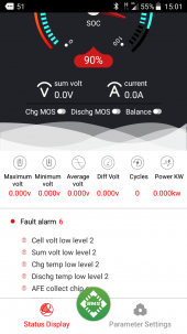
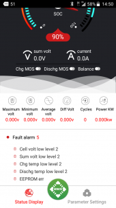
I then moved the BMS to where its permanent home would be and then reversed the procedure. hooked up the B- and then the P- and plugged in the lead connector and pushed the light board button to turn it on. the Bluetooth loaded, showed a bunch of error codes and would not respond after that. tried unit reset, no go, tried factory reset, no go. below are is the codes it tossed. i think its toast.
looked at it all and decided it must have been inrush current that damaged it. broke out spare BMS. doubled checked all wiring, opened inverter disconnect this time (duhh?) and plugged in the BMS. it works! double checked all functions, reset all parameters and then went to hook up the solar controller. it has a bit of inrush, so I used a jumper cable direct from the batter to bypass the BMS to avoid inrush on it. Hooked up the jumper, solar controller came on, flipped breaker and removed the bypass jump cable. double checked all functions, no problems, then flipped the breaker to the panels. stated charging, once again no issues. GTG. moved on to the inverter it has a really big inrush so I once again used a jumper cable to the batter bypassing the BMS to preload it then flipped its disconnect to the on and removed the jumper. this time got the exact same codes out of the bms toasted number two!... now I am awaiting the resistors i ordered form amazon last week so that I can try it one last time with my last spare BMS..
the biggest issue i see is that if inrush can damage it, what happens when the BMS disconnects the output or input and then reconnects? it seems to me that it would have inrush then as well and do the same thing. and better yet why didn't it give me these fits the first time?
When you hook up the B-P- regardless of what's hooked up in so far as charge or discharge, nothing flows through the unit as it can't turn on without the BMS leads attached. its once you attach them and it turns on that is the issue. This time it is basically my own fault as I should and do know better, but as I had not had this issue when I first hooked it up I got complacent... later I was asking other what size resistor they used as I thought it could be an issue. should of said bump it and just waited.It does sound as if the lack of precharge when connecting the inverter fried it, since you didn't have the balance leads connected (that supply power to the BMS).
Yes, connecting the B- first, but connect P- last, preferably with a precharge of the inverter.
Daly has basically zero documentation, and customer support sucks.When you hook up the B-P- regardless of what's hooked up in so far as charge or discharge, nothing flows through the unit as it can't turn on without the BMS leads attached. its once you attach them and it turns on that is the issue. This time it is basically my own fault as I should and do know better, but as I had not had this issue when I first hooked it up I got complacent... later I was asking other what size resistor they used as I thought it could be an issue. should of said bump it and just waited.
These things seem to be poorly designed in some ways, but I think the real problem is lack of a manual that has any actual information. Most of this could be avoided. if it can't handle this then simply put it in the manual. automatically include the light board dongle so folks do not have to dick with it to turn on. things like that are minor but you get the point I think.
to give you an idea about them, I have three of the same model, except they are not the same. one has threaded screws that holds on the B-and P- plates. the other two have nut and bolts to hold on those plates. i think part of the problem might be that DALY themselves farm out work to other factories and the quality control is not the same.Daly has basically zero documentation, and customer support sucks.
But from 120 to 250 or so amps, they are (surprisingly) quite good and not a lot of competition. The JBD 150 amp model (if you are talking a 12v pack) is likely better if that amperage meets your needs, but requires more work since it doesn't include B- or P- leads.
Daly doesn't help themselves by using a chip only they seem to have a datasheet for (12v models), constantly changing the design, and only putting out worthless documentation. It's not like they are a cheap product either.
Their newer models now include a reset switch on the included Bluetooth dongle, likely too many returns of functional BMS simply because Daly doesn't tell you how to do anything. They seem intent on shooting themselves in the foot.
I did the precharge setup in this thread: https://diysolarforum.com/threads/my-push-button-pre-charger-install-for-the-sw-4024-inverter.20426/When you hook up the B-P- regardless of what's hooked up in so far as charge or discharge, nothing flows through the unit as it can't turn on without the BMS leads attached. its once you attach them and it turns on that is the issue. This time it is basically my own fault as I should and do know better, but as I had not had this issue when I first hooked it up I got complacent... later I was asking other what size resistor they used as I thought it could be an issue. should of said bump it and just waited.
These things seem to be poorly designed in some ways, but I think the real problem is lack of a manual that has any actual information. Most of this could be avoided. if it can't handle this then simply put it in the manual. automatically include the light board dongle so folks do not have to dick with it to turn on. things like that are minor but you get the point I think.
I recommend the JBD if they have a model with the current capacity and cell count that meet your needs.so Daly looked at the screen shot I took of the BMS and they said it was due to a high voltage event. I am guessing the inrush to charge the inverter but who knows. got a couple more o play with and I am done with Daly looking at the chargery system as we speak, but will give the DALY one last chance. it was working fine prior to unhooking it to move the battery bank and the BMS wires... guess I get the chance to tear apart a daly to look inside to see where the magik smoke leaked from.

 diysolarforum.com
JBD, that the same as overkill correct? last I checked they did not have anything in the range I need. currently I could use what they offer, but if everything goes according to plan I will be doubling from 400 A/h to800A/h battery pack next spring along with an additional 4kw of solar to power my water heating project so I would need the higher capacity of the Chargery. and honestly i sent Chargery an email and they responded back in four hours which is a new record for me when dealing with Chinese companies. just trying to decide if I want common port of dual port at this juncture. I might have two brand new unopened Daly's for sale with all the options if I pull the trigger on the Chargery.I recommend the JBD if they have a model with the current capacity and cell count that meet your needs.
Chargery is more difficult to set up, but of course they actually have a manual.
Yes, Overkill is a JBD with additional testing and support.JBD, that the same as overkill correct? last I checked they did not have anything in the range I need. currently I could use what they offer, but if everything goes according to plan I will be doubling from 400 A/h to800A/h battery pack next spring along with an additional 4kw of solar to power my water heating project so I would need the higher capacity of the Chargery. and honestly i sent Chargery an email and they responded back in four hours which is a new record for me when dealing with Chinese companies. just trying to decide if I want common port of dual port at this juncture. I might have two brand new unopened Daly's for sale with all the options if I pull the trigger on the Chargery.
this time lag between the US and japan kills meYes, Overkill is a JBD with additional testing and support.
JBD has many models, depends on the voltage for your packs.
JBD Battery PCB Board Store - Amazing prodcuts with exclusive discounts on AliExpress
Discover the wide range of from AliExpress Top Seller JBD Battery PCB Board Store.Enjoy ✓Free Shipping Worldwide! ✓Limited Time Sale ✓Easy Return.www.aliexpress.com


Hi,I use smart BMS Daly 8s 24v 100/100A with battery lithium po4 24Volt 200Ah.
I have a problem
The SOC percentage while charging will no more than 14.7%, but the battery Volt increases until the battery is full (28V), but the SOC percentage while charging will no more than 14.7%.
Please advice.
View attachment 59682View attachment 59683View attachment 59684
this 65535 is it some sort of a magic number?..or you just need to enter a random huge number...i put a 6 digit random number in mine...no issues so far..2nd day runningI always use the lightboard now. But since resetting the sleep timer I do not need it.
Once you have the bluetooth working on your phone. Under parameter settings is something called
"sleep waiting time"
Punch in the number 65535
then click "set"
The password [if needed] is
123456
The S will appear on its own.
This will set the sleep time to forever on.
Yes, it is a magic number in binary. If you enter an arbitrary number, you will get arbitrary results.this 65535 is it some sort of a magic number?..or you just need to enter a random huge number...i put a 6 digit random number in mine...no issues so far..2nd day running