FilterGuy
Solar Engineering Consultant - EG4 and Consumers
I am guessing it is a smaller tank with only one element..... This is not conducive to direct-to-water like I drew before.Im not tied to the grid (boat system).
water heater is AC


I am guessing it is a smaller tank with only one element..... This is not conducive to direct-to-water like I drew before.Im not tied to the grid (boat system).
water heater is AC
Then the inverter would power the water heater load along with the other loads. I would not call that a dump load in the sense that it is not wired like the diagram @FilterGuy posted. Depending how the inverter was programed it would get the power it needed from available solar supplemented by the batteries. If there is a relay involved it may be programmable.not tied to the grid (boat system).
water heater is AC
I think of dump load as different than direct-to-water.Then the inverter would power the water heater load along with the other loads. I would not call that a dump load in the sense that it is not wired like the diagram @FilterGuy posted. Depending how the inverter was programed it would get the power it needed from available solar supplemented by the batteries. If there is a relay involved it may be programmable.


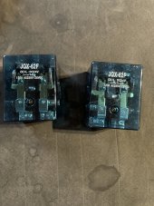
Hopefully the contacts are DC rated.I have changed my 40gal electric water heater to 24v Dernord heaters, hooked in parallel through an 80A motor contactor. .....
Do you use a tempering valve? I use one on my heat pump water heater to effectively increase its storage capacity. I only set mine to 54 C but the tempering valve mixes the outgoing water so there is no risk of scalding.Having about 12kw useful battery life I can get the water warm enough for a comfortable shower in most conditions, but keeping it set at 71C the tank will stay hot for several days without any additional power if I thermostat out on a good sunny day.
Spoke to an EE doctorate and he advised I derate the contactor and sent me a chart. At lower DC voltages it said derate by .5-1 (half to none) hence the 80A contactor... which is twice the current passing through and using two of the poles to connect the battery instead of 1. The new dpdt relays are DC rated and overrated.Hopefully the contacts are DC rated.
Do you use a tempering valve? I use one on my heat pump water heater to effectively increase its storage capacity. I only set mine to 54 C but the tempering valve mixes the outgoing water so there is no risk of scalding.
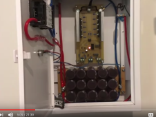
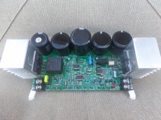
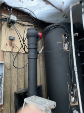
Hello,There is successful and then there is really successful. With enough space and panels heating water isn't a problem. I do diversion heating directly from array voltage and not using a battery or charge controller by diverting any increment of unused power not needed for charging. I have a 40 gallon tank in the garage just used for the clothes washer. All laundry cycles use hot water, it's free. This is excess diversion from diversion system that heats the house water. This is just an example of what can be done. I know there are lots of used panels, but think of how that separate hot water array could be used for household needs.
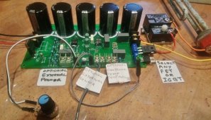
12V panels with a 12V heating element is always a bad match. A heating element closer to 18V or higher should be used. 24V panels will match closer to 36V elements. You don't want to over voltage elements. Dual element heaters can be placed in series instead of parallel shorting bars. This increases your resistance options. I use 2,000W 120V elements, these are 500W at 60V. There is an ideal resistance, but that is only useful if you live where there are no clouds. If the panel can produce 10A max, 7.5A would seem pretty good. Fact is the power has dropped to 50%. At 5A it id down to 25%. Some studies have shown increasing ideal resistance 50% does not affect daily power production that much and is a big help on those partly cloudy days.
I use power point control to always get what the panels can produce. I have very limited space. A number of panels are not even on my property. I keep them at a low angle almost flat so they can't be seen. All the panels suffer from extreme shading and I have to clean off twigs every morning because they are under trees. It is a site that shouldn't work art all. And I have hot water.
It exist in my country, PV with water flowing behind them, it's not efficient and the cost make them only usable when you lack space for your PV.This paper reminded me of this thread: Performance of a Solar-Assisted Air Source Heat Pump in Heating Condition [zhou2010] it's about heating indoor air but applies to water heating just as much.
Reviewing options:
Solar Thermal Source Heat Pump can use either dedicated solar concentrator or be integrated into the back of photovoltaic panel.
- Joule Heating: resistive element in water tank
- Air Source Heat Pump: pump heat from outdoor air into water
- Solar Thermal Source Heat Pump: pump heat from solar concentrator into water
- combination of all the above
My ideal solution would be a photovoltaic panel with heat exchanger on back. During winter pump supplemental heat out of them to harvest otherwise wasted solar thermal energy. Bonus: photovoltaic production will increase due to temperature coefficient of most panels...
This would allow the air heat harvesting device ("condenser") to be smaller
View attachment 59488
 dualsun.com
Make a differential cutter (GFCI?) built for DC. A DC current shunt in each leg with their outputs connected to cancel eachother out. If one side draws more current than the other, you'll get the differential voltage to trigger your safety disconnect with. The circuit details so far as output isolation are more involved, but that's the basic idea. Hall effect sensors might work too, but I'd trust current shunts more.Hello,
I'm thinking of many solutions to heat my water, for some month now, I end up with the idea of putting a bunch of resistors (elements) of different internal resistance in parallel with mppt/inverter (Chinese all in one 5kw) connected to the panels. I had the idea of using a pilot panel to guess the available power (using Arduino to control all that) and connect those resistors depending on the guessed power available.
My main problem is that my strings are 200V/10A, I could use (I'm in Europe) 230V element BUT...there is no way to secure the electrical circuit with a differential cutter ...cause it's DC. And that is a problem, I do not want to die of electrocution in 15 years when the element will be old and maybe contact with the heater chassis (ground may not be enough to save me)
So....the idea of using a buck converter to convert the 200V/10A To something "harmless", a dirty alternative current or a lower voltage dc (maybe 48V) arised in my head.
I then searched forum...and find this discussion.
So, did I understand correctly, you use a buck converter paralleled with your mppt/inverter and panels, how the buck converter only take unused power.and do not "steal" from the inverter.
Is the mppt still able to work and put the string in the mppt mode...?
Is the solution you actually use a mature one or does it still have main caveat..?
Do you sell board, schematics... or do you give schematics for free...?
I'm sorry for so many questions...?
My other solution is to use the AC from the inverter, guess the available PV power from the pilot panel, a sensor on the AC output to guess the used power, a shunt on the batteries and voila...
I was thinking of making a nice algorithm that would feed a database and improve itself Everytime the shunt detect a use of the batteries. Current flow.in the wrong direction in the shunt --> cut heater immediately.
Now...this idea got a big problem....if the inverter die...I got no hot water (well...I got a wood boiler, but let's 0ush it aside) and it annoy me...
Make a differential cutter (GFCI?) built for DC. A DC current shunt in each leg with their outputs connected to cancel eachother out. If one side draws more current than the other, you'll get the differential voltage to trigger your safety disconnect with. The circuit details so far as output isolation are more involved, but that's the basic idea. Hall effect sensors might work too, but I'd trust current shunts more.
You can feed the solar directly into the DC element, just disconnect a number of panels from the battery to feed the element, you can do that any way you like. You can also do that via the inverter, but why tax the inverter and incur the losses if you do not need to.ahh never quite understood that. Have not found DC elements for the hot water tank/heater i have. so would assume in that case its a relay off the AC inverter ?
Hello,Make a differential cutter (GFCI?) built for DC. A DC current shunt in each leg with their outputs connected to cancel eachother out. If one side draws more current than the other, you'll get the differential voltage to trigger your safety disconnect with. The circuit details so far as output isolation are more involved, but that's the basic idea. Hall effect sensors might work too, but I'd trust current shunts more.
This 10mA things depends of course on the voltage. In my country, in France, we use 30mA, it's the code, it's everywhere in the house, for all "lines" of conductors. We use 230 VAC/50Hz.Hall effect seems to have a large offset. I have to keep zeroing the DC clamp scope probe I use.
Shunt - how much error in each?
If carrying 10A DC, want to detect and shut off for about 10 mA or above, because something in that range or slightly higher causes involuntary muscle contraction (can't let go), and above that death. At least for AC, we use 5 mA in the U.S. for GFCI. In Europe, 30 mA for whole-house GFCI (but that's a level where muscles contract.) Might be a different physiological limit for DC.
Probably difficult to ensure < 0.1% difference in measurement error between the two DC shunts.
For AC, the two wires go through a magnetic core, fields cancelling each other, and only common-mode is coupled to sense line. I think that does a better job of detecting small differences. We have 30A, maybe 50A GFCI designed to detect 5 mA leakage so 0.01%
This 10mA things depends of course on the voltage. In my country, in France, we use 30mA, it's the code, it's everywhere in the house, for all "lines" of conductors. We use 230 VAC/50Hz.
If there is a current leak, higher then 30 mA which is something like 7 watts, this part of the circuit is automatically cut off from the system.
| Fréquence | 50 Hz |
| Tension nominale | 230 V~ |
Same system in South Africa.This 10mA things depends of course on the voltage. In my country, in France, we use 30mA, it's the code, it's everywhere in the house, for all "lines" of conductors. We use 230 VAC/50Hz.
If there is a current leak, higher then 30 mA which is something like 7 watts, this part of the circuit is automatically cut off from the system.
I just added this separate 40 gallon tank in the garage just to wash clothes.
![IMG_1623[1].JPG](/data/attachments/69/69137-0b83f72b2ec9333f8bb5f03a86136d3e.jpg)
")