Anyone got any further input as to what the "actual" torque wrench setting would be to get to the 12ft/lb in the eve280 specs?
here is the tricky park with that question when looking at the EVE fixture spec and how I am reading what they are TRYING to tell us...
From the EVE 280Ah spec version E page 4/11 we get ONLY the following:

Notice it mentions a
fixed FORCE; it does not say 300kgf at 30% and <some other>kgf at 100%; it just says a 300kgf is applied.
We can derive the PSI (whichis a force over an area) by looking at the same spec and getting the area of the cells so that is how we get to PSI.

so now we have a
FIXED force per square inch.
the next issue is the spec clearly states the
THICKNESS of the cell WILL change (ref page 4 of spec):

so the challenge is how to maintain a FIXED force across a battery in a fixture that WILL expand.
Worst case expansion of a NORMAL battery is:
(71.5mm - 1mm) = 70.5mm at 30%SOC
(72mm+1mm) = 73mm at 100% SOC
====UPDATE===
others have pointed out below that what the spec sheet
really means is that the expansion due to charging is only 0.5mm (that is 20thou of an inch); the rest of the +/-1 is manufacturing tolerances. This could be, however, measuring my cell actually expand more than 0.5mm and they are grade A eve cells so not sure what to make of it..could still be a variance which means over a series fixture of many cells it should "average out"...
============
so the battery WILL change its width by 2.5mm PER CELL and that is
normal!
A 24v-8cell battery pack in a series fixture will increase its overall length by (8 * 2.5mm) = 20mm or 0.78in when charged from 30% to 100%
this is why you need to be careful on using a RIGID fixture if you are trying to follow the spec; if the cell fixture is rigid the pressure will get quite high as it is normal for the cells to expand when charged, you must actually let them expand.
basically you need to design a system that provides 300kgf at 30% capacity AND a 300kgf force at 100% capacity.
This is why engineered linear compression springs are important as they provide a true spring constant(lbs/inch of travel) so you can actually calculate what will happen to your battery pack as the series cell expands.
I use engineered foam spacers every other cell (so each cell has at least 1 foam side to push against) AND springs so that cells can still expand while the springs are continuing to provide a known force (but not to much force hehe)
another option is if your cells spend most of their time charged, well, make sure to apply the 300kgf when at 100% and for the time when cells are disharged let the pressure drop a bit ;-)


 I decided on using four 160# die springs, I set them at 11.6psi at 50%soc. Based on the expected expansion they should be in the sweet spot. I was worried just clamping with no room for expansion that the pressure could build over the max recommended.
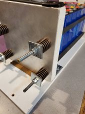
") ), the +/- 1 mm is just a manufacturing tolerance, the expansion will be around 0.5 mm between 30 and 100 % no matter what.
), the +/- 1 mm is just a manufacturing tolerance, the expansion will be around 0.5 mm between 30 and 100 % no matter what.

