diy solar

diy solar

EVE-280 cells should these be clamped tight or spaced for expansion?

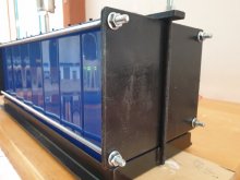
What someone could do is take a scale and sandwich it at the end of 16 cells compressed by threaded rods, then charge the cells and see if the pressure changes.

My current plans for my portable kit includes something along these lines. Although it won't be particularly well-calibrated... mostly to satisfy my curiosity in how cell pressure changes relatively over the course of the charge cycle.

I'm still working out the details and it depends on whether it all works out. Right now it's "iffy" and this feature might face the chopping block. I managed to roughly calibrate the pressure pad with a roughly-calculated fitted curve but it turns out trying to read a resistance range in megaohms is a challenge on an arduino. I have another trick up my sleeve though...
 
Could I ask, what setting on the torque wrench equals the 12psi. Is it 3 in/lb per nut? I not doing the springs.
 

Attachments

  • 20201114_101748.jpg
    20201114_101748.jpg
    55.6 KB · Views: 113
Well I pop up in this ongoing thread sop I'll post a link to the description of my Battery Pack assembly for anyone interested.
The "Boxes" I built keep the cells snug (the sets had to be "pressed" into the box).
I'll also mention that even when top balancing independent cells to 3.65V until the amperage drops to 2A taken (so genuinely full) I put the cells between clamps because they do swell up a little when charging them... I just did 4 new 280's charging each cell with 3.65V/30A CC/CV...

Pg:2 https://diysolarforum.com/threads/m...n-ontario-canada-24vdc-120vac.1484/post-12603
 
Mine swell up a little too and I am charging at 12 amps. I wonder how much the C rate effects swelling when charging?
 
Could I ask, what setting on the torque wrench equals the 12psi. Is it 3 in/lb per nut? I not doing the springs.
Depends on how flexible your end plates are and how stretchy your threaded rods are. You could model everything mathematically, but even with a 100% accurate model, I still wouldn't trust it very far. That is why I am going to use a load cell and a torque wrench and measure it with my setup. Different components are going to behave differently so I would be very careful about assuming that a value that works in somebody else's system is going to work the same in yours unless your system is an exact duplicate of theirs.

What are you planning on doing to ensure the nuts don't loosen? Lock washers? Locknuts? I am planning on using flange nuts with an extra jam nut on top to prevent them from loosening from vibration. A lock washer or a locknut would interfere with measuring the torque on the nut. They would also make torque measurement unrepeatable (it takes more torque to tighten a locknut the first time than it does on subsequent times and each time you loosen and retighten it takes less torque to spin the nut on the bolt).

If you are not using springs, then I would be very careful about how snug you make your nuts. 8 cells in a stack is going to behave very differently than 4 cells in a stack. The reason I am using springs is to provide a safety mechanism to prevent crushing cells at full state of charge.

-Edit-

After reading what I just wrote, the idea of just wrapping the cells tightly with filament tape is looking better and better. If measuring force wasn't what I do for a living, I don't think I would be willing to do this at all. In my case this particular exercise is right up my alley. Depending on what I learn, the end result might be that I end up not doing any of this.

I think the rest of you guys are kinda nuts to be doing this, since you really don't know what compressive force you are putting on your cells. This is a situation where the advice "first do no harm" really does make a lot of sense. Too much compression could be worse than not using compression at all.
 
Last edited:
The clamping force of a threaded fastener is not dependent on the length of the rod. The only factors that matter in clamping force on a threaded fastener are coefficient of friction, thread size/pitch, and torque.

You can dig through the other thread on clamping. But we discussed at length how to figure out the correct torque for various size fasteners. There are numerous web-based calculators for calculating the clamping force of a nut or bolt based on the applied torque.
A threaded rod is a spring and the longer the threaded rod, the lower the spring constant is of that rod. The end plates are cantilevered and subject to flexing (creating another spring). Both of these will have an effect on the clamping force the threaded fasteners apply to the cell.

Theoretically you are correct, that the clamping force of a threaded fastener is determined by those factors. What is the coefficient of friction of a nylon locknut? Or a nut compressing a toothed washer?
 
It doesn't matter what the spring rates are, if your finishing torque is X and your thread is Y, the clamping force will be Z. If using a lock nut, measure the free torque and add it to the target value.

Now if you are talking about how the clamp load changes over SOC, that is dependent on numerous factors. However most folks seem to be content with tightening at higher soc and calling it good.

As mentioned the best approach seems to be coil springs under the nuts, which produces very consistent clamping.
I am concerned that the clamping fixture I use maintain pressure on the cells within my defined limits from 0 to 100% SOC and over temperature from 0 to 40 degrees C.

I plan on exploring how Belleville washer springs work in this application. I would be willing to test coil springs also. Got a recommendation for a set of springs to use to compress a 4 cell stack? If anyone has an extra set of springs they are willing to donate I would appreciate that. I already have Belleville washers on order. I probably ordered 10 times as many Belleville washers as I am going to need if they work out and anyone wants a set.

Just to give you an idea of what I do. I have been working in a technical role in the force measurement industry since the late '70s. I am not an ME (I am an EE and also write firmware), but I do have some slight idea of what I am talking about with respect to measuring force. These are my last two employers. I was with MT for over 30 years.

www.interfaceforce.com
www.mt.com
 
I think I need a copy of that book "Mathematics for Dummies".
Because surely my math must be incorrect!

Given:
1) the 280ah cell face is about 7" X 8" which equals about 56 square inches
2) the recommended force to be applied is 12 pounds per square inch
3) ( 12 pounds per square inch ) X ( 56 square inches ) = 672 pounds

Given:
1) EVE recommends 300 kgf
2) Kilogram-force is the weight of a kilogram under standard gravity
3) 300 kilograms = 661 pounds

Is that 300 kgf per cell?
If so does that imply four adjacent cells ( 4S 12 volt pack ) would require 2,644 pounds of clamping force?
Or 660 pounds of pressure on the stack?
Either way that's a lot of weight!
Seems like too much...

Screenshot 2020-12-29 at 4.30.09 PM.png

I'm so confused :unsure:
 
Last edited:
Two rows of cells would need double the clamping force. Obviously design your fixture to make it fairly even.
 
  • Like
Reactions: Dzl
Measure clamping force
I am waiting for 16pcs Lishen 280Ah cell. I also want to clamp my cells with threaded rods + alu and wood.
My BMS will be a ESP32 and thinking about using this for measuring the clamping force:

hx711.png

A HX711 with 4x50kg sensor. ( You can get them for about Eur 6,- at Banggood or Aliexpress)
I will start with total 150kg force (0.44 kg/cm2= 6.3PSI) and can then measure what happens with the force during charge and discharge.
 
SOURCE: Convert Kilogram Force Centimeters to Newton Meters (kgf cm to Nm) | JustinTOOLs.com

300 Kilogram Force Centimetersto common torque units
300 kgf cm= 29.41995 newton meters (Nm)
300 kgf cm= 3 kilogram force meters (kgf m)
300 kgf cm= 300 kilogram force centimeters (kgf cm)
300 kgf cm= 21.699041526925 foot pounds force (lbf路ft)
300 kgf cm= 21.699041526925 pound foot (lb ft)
300 kgf cm= 294199500 dyne centimeters (dyn cm)
300 kgf cm= 698.14601657448 foot poundals (ft pdl)
300 kgf cm= 260.3884987072 inch pounds force (in lbf)
300 kgf cm= 0.02941995 kilonewton meters (kN m)
300 kgf cm= 29419950 meganewton meters (MN m)
Kilogram Force Centimetersto Pound Force Foot (table conversion)
1 kgf cm= 0.072330138423083 lbf ft
5 kgf cm= 0.36165069211541 lbf ft
10 kgf cm= 0.72330138423083 lbf ft
20 kgf cm= 1.4466027684617 lbf ft
30 kgf cm= 2.1699041526925 lbf ft
40 kgf cm= 2.8932055369233 lbf ft
50 kgf cm= 3.6165069211541 lbf ft
60 kgf cm= 4.339808305385 lbf ft
70 kgf cm= 5.0631096896158 lbf ft
80 kgf cm= 5.7864110738466 lbf ft
90 kgf cm= 6.5097124580774 lbf ft
100 kgf cm= 7.2330138423083 lbf ft
200 kgf cm= 14.466027684617 lbf ft
300 kgf cm= 21.699041526925 lbf ft
 
Don't crush your batteries
Optimal is:
300kg on about 340cm2 (170*200mm)
300kg/340cm2 = 0.88 kg/cm2 = 12.5 PSI
I start with half that value, what should give 80-90% of max live cycles and gives me some measering range.
 
Just FYI about my 280Ah LISHEN cell and Liitokola after i watch thsi video:
I just check the Voltage between the case of the cell and the Negative terminal, it shows the same Voltage reading as when measure between Positive terminal and the Negative terminal, 0V between Positive terminal and the case.
So I do the same test with the 90Ah Liitokola and get the same result.
I put 100 Ohms resistor on Negative and the case, the Vdrops on the resistor is 1V, = 10mA.
That is not low leakage.
I plan to put insulation sheet between the cells when I wrap them up. With this result, it will be bad case for mobile application if cells are not separated with tough insulation, I would not trust the PVC wrapping either. So if you strap them tightly, make sure to add insulation sheet between cells.
 
Back
Top