diy solar

diy solar

EVE-280 cells should these be clamped tight or spaced for expansion?

It seems as though there are an infinite number of ways to build a fixture for a 4s 280ah battery.
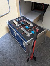
FWIW this is the approach I took...
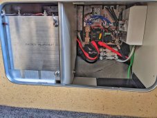
PXL_20210427_203323810.jpg

PXL_20210427_003351739-01.jpeg

This battery is for my van camper which I primarily use during the summer to escape the desert heat of southern Arizona. I wanted to be able to easily remove the battery when the van is not in use for the 8 months I spend at my winter home. During the shoulder seasons the temperature in the van regularly exceeds 100 degrees - which is not good for the battery!

Space constraints dictated the design, in particular the overall length. IMHO this design offers some advantages over other approaches. For example: the threaded rod in combination with the binding barrels reduces the overall length and takes some of the guesswork out of 'fixture compression'. The components I used resulted in about the right amount of compression. IE: After the pack is fully assembled you tighten the binding posts all the way, this puts an equal amount of compression on the pack, no need to guess how much torque to apply to the nuts on the threaded rod. If you need more or less compression simply add or remove some washers.

I felt it was important that the threaded rod & binding posts be manufactured with tight tolerances, which I believe these are. It was not necessary to modify the length of the threaded rods. The 8" x 8" aluminum plate works out to be just the right size. So all you need is a hand drill to make the holes in the end plates and a pair of scissors to cut the foam & neoprene separators.

I read somewhere on this thread that Norseal was recommended to use between the cells. The silicone foam I chose had very similar characteristics to what was recommended at about 1/3 the cost. I placed that material between the cells and placed neoprene on the aluminum end plates. The end result is a fairly compact monolithic block that exhibits no lateral flexing or twisting...

Silicone foam comparison:
$25 vs $79 for a 12 x 12 sheet.
Pressure to compress to 25% 7 PSI vs 9 PSI
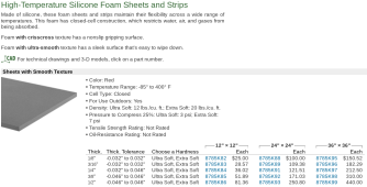
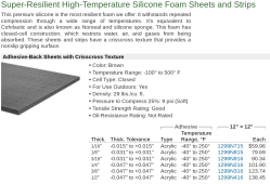
Screenshot 2022-01-10 12.03.00 PM.png

Screenshot 2022-01-10 12.04.40 PM.png

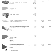
The total cost for this approach is quite high! McMaster Carr sells premium products at a premium price! However - as I said - space constraints forced me to keep the overall length to an absolute minimum. No doubt some of the components could be substituted with something less expensive. I present this BOM as a guide for what to consider when choosing components.


Screenshot 2022-01-10 10.15.14 AM.png
 
Last edited:
In example “C” of post #708; using one plate to compress more than one set of cells and dividing the compression force equally between the number of compression points would result in not compressing the outer edges of the cells enough and the inner edges too much.......if there is deflection in the plate.....and there is almost always some deflection.
This is backwards. The outer edge of each pack would be seeing 440 lbs total (220 x 2) but the inner edges would be seeing 440lbs (220 x 2) but that 440 would be shared between both packs. The inside "edge" of each pack would see a total of 220lbs while the outside is seeing a total of 440lbs. This is the opposite of what is in bold above.
 
This is backwards. The outer edge of each pack would be seeing 440 lbs total (220 x 2) but the inner edges would be seeing 440lbs (220 x 2) but that 440 would be shared between both packs. The inside "edge" of each pack would see a total of 220lbs while the outside is seeing a total of 440lbs. This is the opposite of what is in bold above.
I see that it is backwards, thank you for pointing that out.
 
What I haven't seen is any test data or manufacturer recommendations that consider compression and C-rate at the same time. EVE's newest 280Ah cell is tested at 0.5C, it would be interesting to check if their compression reccomendation/estimates are the same or different in this newest datasheet LF280K.
The LF280K datasheet is available here: https://www.evebattery-germany.de/wp-content/uploads/2021/11/LF280K-Product-Specification.pdf

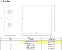
They still specify a 300 (+/-20) kgf clamp in the cycle rating tests. Thickness is also specified under this clamping force; 72 +/-1 mm for a single cell and 72 +/- 0.5mm average over 200 cells at 30-40% SOC. Also unlike some older datasheets they do not specify a cycle rating without a clamping force.
 
  • Like
Reactions: Dzl
If you do clamp cells together, you best use a compliant spongy pad between cells to prevent high pressure points on cells.

Cell layers wrappings are not uniformly flat. Just aluminum end plates clamping cells together is likely to create very high pressure points on cells' surfaces. Cell separator layers between neg anode and pos cathode electrodes is a thin polymer plastic film with very small, perforated holes to allow lithium ions to pass through. With enough pressure point it can be crushed to the point of creating a short circuit within cell.

This is why I am against DIY'ers clamping cells. What you might gain versus what you might lose is not favorable.
Yeah, I'm on board with that argument. For me personally I'm going to put my bank on a boat, so I do need some kind of secure fixturing and vibration dampening for the cells, and foam of some kind is looking like a pretty good option.
 
The LF280K datasheet ...unlike some older datasheets they do not specify a cycle rating without a clamping force.
And the LF280K Cycle vs. capacity curve with 300kgf clamping force is much more linear than the 2019 version (maybe two versions back?) with clamping force, which actually lost more capacity over the first ~1500 cycles than without any compression "fixture".
 
The LF280K datasheet is available here: https://www.evebattery-germany.de/wp-content/uploads/2021/11/LF280K-Product-Specification.pdf

They still specify a 300 (+/-20) kgf clamp in the cycle rating tests. Thickness is also specified under this clamping force; 72 +/-1 mm for a single cell and 72 +/- 0.5mm average over 200 cells at 30-40% SOC. Also unlike some older datasheets they do not specify a cycle rating without a clamping force.
Let me try to convert… 300kgf (kilogram foot pound) 260 inch pounds or 21.7 foot pound. Correct??
 
If you do clamp cells together, you best use a compliant spongy pad between cells to prevent high pressure points on cells.

Cell layers wrappings are not uniformly flat. Just aluminum end plates clamping cells together is likely to create very high pressure points on cells' surfaces. Cell separator layers between neg anode and pos cathode electrodes is a thin polymer plastic film with very small, perforated holes to allow lithium ions to pass through. With enough pressure point it can be crushed to the point of creating a short circuit within cell.

This is why I am against DIY'ers clamping cells. What you might gain versus what you might lose is not favorable.
Let me comprehend for 4 cell bank….$50 for your suggested spacers…. And compress to whatever psi on maybe 6 rods, (3 per side) and results will be within compression specifications of 300kgf (kilogram foot pound) 260 inch pounds or 21.7 foot pounds?
 
Let me try to convert… 300kgf (kilogram foot pound) 260 inch pounds or 21.7 foot pound. Correct??
No, kgf is just kilograms of force. 300 kg is 661 lbs, so 661 pounds of force (lbf). It's not a torque or a pressure measurement, it's just a force. Like if you just put a weight of that size on the batteries.
 
kgf = kg of Force
inch pounds or foot pounds are torque or force over distance, not directly applicable in this case.
It works out to about 12 psi pressure (optimal) on the wide sides of the cells.
 
Last edited:
I do believe I understand what you are saying, I may not be doing a good job of explaining.

If you have 1 row of cells you have the 660 lbs. 330 lbs on each side, 165 on each rod:

View attachment 77824

If you have 2 rows of separate cells you would now have 8 springs total. Each separate plate seeing 660 for a total of 1320 lbs:

View attachment 77826View attachment 77827

You now want to join the plates together and eliminate one of the two rows of springs in the middle but you must maintain the the 1320lbs.
What you have suggested is that you should just average the 1320 over the 6 springs so each would be seeing 220lbs. Why would you do that? That force was in that location for a reason. Why would you all of a sudden decide the outside of the cells need more force simply because you changed the number of springs?


View attachment 77825

If you left the 4 springs in the middle of the pack you would still average the 1320 over the 8 springs and each would still have 165lbs on each rod. You have now eliminated 2 springs from the middle. The remaining middle two springs need to make up that pressure loss in that location.

As I said in the last post, if you dont think deflection is an issue, you can average out. If that is the case then why even have 6 springs? Just use 4 springs, two on each side that each see 330lbs and call it a day. You still have 1320lbs but I suspect that most people will not think that is such a good idea. Having the middle row helps even out the force. If you are going to go to the trouble of adding the middle row of springs, why not take out any deflection possibility and make the tiny extra effort and simply make sure the force is being applied evenly to each side of each row of cells.

To answer you question directly: Each rod on the outside of the pack would still see 165lbs. The rods that are between cells would need to see double that so 330lbs because they are working acting on two sets of cells, not just one.
One thousand three hundred thirty pounds? WTH! I’m still confused about amounts of compression needed! EVE280 specifications show 300kgf (kilogram foot pound) 260 inch pounds or 21.7 foot pound is what they used. Please clarify. Thanks
 
No, kgf is just kilograms of force. 300 kg is 661 lbs, so 661 pounds of force (lbf). It's not a torque or a pressure measurement, it's just a force. Like if you just put a weight of that size on the batteries.
So, I’m practice how does one achieve those specs on a four cell bank?
 
So, I’m practice how does one achieve those specs on a four cell bank?
You probably shouldn't, as has been recently discussed, but if you really do want to do it, the entire thread is full of ideas on how to do it and there's several other threads about it too. Try reading a bit?
 
It seems as though there are an infinite number of ways to build a fixture for a 4s 280ah battery.
FWIW this is the approach I took...

View attachment 79104

View attachment 79109

This battery is for my van camper which I primarily use during the summer to escape the desert heat of southern Arizona. I wanted to be able to easily remove the battery when the van is not in use for the 8 months I spend at my winter home. During the shoulder seasons the temperature in the van regularly exceeds 100 degrees - which is not good for the battery!

Space constraints dictated the design, in particular the overall length. IMHO this design offers some advantages over other approaches. For example: the threaded rod in combination with the binding barrels reduces the overall length and takes some of the guesswork out of 'fixture compression'. The components I used resulted in about the right amount of compression. IE: After the pack is fully assembled you tighten the binding posts all the way, this puts an equal amount of compression on the pack, no need to guess how much torque to apply to the nuts on the threaded rod. If you need more or less compression simply add or remove some washers.

I felt it was important that the threaded rod & binding posts be manufactured with tight tolerances, which I believe these are. It was not necessary to modify the length of the threaded rods. The 8" x 8" aluminum plate works out to be just the right size. So all you need is a hand drill to make the holes in the end plates and a pair of scissors to cut the foam & neoprene separators.

I read somewhere on this thread that Norseal was recommended to use between the cells. The silicone foam I chose had very similar characteristics to what was recommended at about 1/3 the cost. I placed that material between the cells and placed neoprene on the aluminum end plates. The end result is a fairly compact monolithic block that exhibits no lateral flexing or twisting...

Silicone foam comparison:
$25 vs $79 for a 12 x 12 sheet.
Pressure to compress to 25% 7 PSI vs 9 PSI

View attachment 79120

View attachment 79121

The total cost for this approach is quite high! McMaster Carr sells premium products at a premium price! However - as I said - space constraints forced me to keep the overall length to an absolute minimum. No doubt some of the components could be substituted with something less expensive. I present this BOM as a guide for what to consider when choosing components.


View attachment 79112
Putting a compressible mat between the cells sounds like a really good idea but once again I’m confused with your decision the specs on the silicone indicates they are 12 pounds per square foot it’s my understanding that most compression is at 12 psi (8-17 psi) any guidance on your choice may help. Thanks
 
...the specs on the silicone indicates they are 12 pounds per square foot...
I think you're looking at the spec for density: 12 lbs/cubic foot.
BTW, foam often has a spec. expressed in lbs. per SQUARE foot, but that is just the weight of a given thickness, e.g.: most carpet underlayment foam is upwards of 10-12 lbs. per square foot.
 
I think you're looking at the spec for density: 12 lbs/cubic foot.
BTW, foam often has a spec. expressed in lbs. per SQUARE foot, but that is just the weight of a given thickness, e.g.: most carpet underlayment foam is upwards of 10-12 lbs. per square foot.
4” of given material, compressed to 3” (25%) is standard rating…. (https://www.foambymail.com/blog/und...rength-and-applying-the-values-to-your-needs/) So how can we possibly convert that into required 3/8 foam specifications?
 
That's 25 percent compression from original thickness. Do the math.
That's 1/4" compressed to 3/16" (compressed by 1/16" or 1.587 mm)
Or sixteen 1/4" thick pieces (4" total) compressed to 3” total.
Or seven 1/4" thick pieces (1.75" total) compressed to 1.3125” total, e.g.: what you'd have with 8 cells together.
BUT the expected compression is about 0.5mm per cell, which is less than that.
So you probably want thinner foam or much stiffer foam than 12psi @ 25%
 
One thousand three hundred thirty pounds? WTH! I’m still confused about amounts of compression needed! EVE280 specifications show 300kgf (kilogram foot pound) 260 inch pounds or 21.7 foot pound is what they used. Please clarify. Thanks
For each row of cells you have you want 660 lbs of "force" If you have 2 rows of cells sharing a side plate then the total force that side plate is exerting is 1320 lbs.

If you look at the sketches below it could help your understanding.
Sorry not to get back to you sooner. Seems that this is a rather intractable problem. I have asked
a couple on engineering friends and they also are not sure which way it should be. The answer seems to be that if there is no deflection in the plate either way will work. If there is deflection then evenly distributing the pressures is probably the way to go. If there is more pressure on the middle of the plate and the plate deflects then over time there will be more pressure on those parts of the plate that are deflecting. One of the engineers is going to do a vector diagram to see how that looks..... I am waiting on that.

I have attached a couple of drawings for clarity:

A is simply one cell with four bolt/springs applying 660 pounds of force on the cell face
B is illustrating two cells and two plates side by side but not attached to each other
C is one plate covering two cells and having evenly weighted bolt/springs applying force
D is one plate covering two cells and having the combined force of the 4 bolt/springs in the
centre of A replaced with 2 bolt/springs
View attachment 78280


The next drawing is how I am trying to arrange a 48 volt series pack with 16 EVE 280 cells. There will be 4 cells wide by 4 deep, bolt/springs represented by the circles, not to scale. The weights on the bolt/springs to be determined.View attachment 78279
 
That's 25 percent compression from original thickness. Do the math.
That's 1/4" compressed to 3/16" (compressed by 1/16" or 1.587 mm)
Or sixteen 1/4" thick pieces (4" total) compressed to 3” total.
Or seven 1/4" thick pieces (1.75" total) compressed to 1.3125” total, e.g.: what you'd have with 8 cells together.
BUT the expected compression is about 0.5mm per cell, which is less than that.
So you probably want thinner foam or much stiffer foam than 12psi @ 25%
Okay let us start at point x. Say 4 cells with 3/16 (0.1875” or for argument sake say 4.5mm) foam. That’s 5 pieces total.

Now each cell expands.5mm per side, resulting in 1 mm “expansion pressure” between the cell’s upon the foam, and.5mm “expansion pressure “ against the aluminum bookends.

Let’s concentrate with the three center foams, and a 25% compression material . Therefore movement from 4.5 would result in 1.125mm.

However I believe one must include the starting pressure (cells bound) as well as the cells SOC.

On theory 4 cells at 50% SOC and torque at say 12psi with 3/16 foam of 25% compression should keep them under the 18psi damage range when fully charged.
Am I missing something?
 
...say 12psi with 3/16 foam of 25% compression should keep them under the 18psi damage range when fully charged.
Am I missing something?

The main thing you may be missing is knowing what the compression curve of any given material looks like.

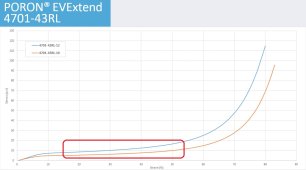
What you want is a foam (or very soft rubber) that maintains a fairly constant compression rate (psi) over a fairly useful range of compression (inches or mm), measured in percentage of original thickness that corresponds to the cell expansion of about 0.5mm (or whatever it actually is). That, and you want it to maintain as close to its original stiffness as possible over the years it will be in service.

As an example, let's say you have foam that is 4mm thick (uncompressed) and it is installed when the batteries are below 30% SOC & then compressed to say, 3mm thick (i.e.: compressed by 25% of original thickness), at which the specs say it exerts 9 psi pressure).
Then when each battery is fully charged, it expands by 0.5mm, and the foam will be compressed to 2.5mm thick (on average), which is compressed by 33% of original thickness, resulting in somewhat higher pressure. In most cases you will only find specs for 25% & 50% compression, but (for example) if the foam exerts 9psi at 25% compression and 15psi at 50% compression, you can be sure it will be a lot less than 15psi at 33% compression.

The other factor is compression set, which is how much of that initial spring pressure is eventually lost when the foam stays compressed a long time. The best foams for this application have long-term compression of less than 10%

This is why the Poron EV Extend was designed specifically for this purpose: it has a pretty flat pressure curve in this compression range
Untitled 1-29.jpg
and very low compression set.
rogerscorp.com/-/media/project/rogerscorp/documents/elastomeric-material-solutions/poron/english/data-sheets/poron--evextend-data-sheet.pdf

But other foams will work OK too.

...each cell expands 0.5mm per side, resulting in 1 mm “expansion pressure” between the cell’s upon the foam...
You'd only count this expansion (basically) once per cell, not twice as in your example above.
Another way of looking at it that each cell expands half of that 0.5mm (or whatever it actually is) in each direction, or 0.5mm total (hypothetically, I guess cells could be prone expanding asymmetrically.
 
Last edited:
The main thing you may be missing is knowing what the compression curve of any given material looks like.
What you want is a foam (or very soft rubber) that maintains a fairly constant compression rate (psi) over a fairly useful range of compression, measured in percentage of original thickness that corresponds to the cell expansion of about 0.5mm (or whatever it actually is).
As an example, if you have foam that is 4mm thick (uncompressed) and when the batteries are below 30% SOC, the foam separators are compressed to say, 3mm (25% of original thickness, at which the foam specs say they exert 9 psi pressure). You may not know

Then when each battery expands

This is why the Poron EV Extend was designed specifically for this purpose: it has a pretty flat pressure curve in this compression range


You'd only count this expansion (basically) ONCE per cell, not twice as in your example above. Or another way of looking at it that each cell expands half of that 0.5mm (or whatever it actually is) in each direction.
I thought EVE304 expanded 1mm (.05mm per side), when placed next to another cell , then each .05 movement upon each side of spacer comes into play. Therefore there’s.1mm of action on each spacer. I agree about using a different one, as the diffusion will be different depending upon thickness and starting compression. Is it generally understood that 12psi applied torque to each rod at 50%SOC ??
 
I thought EVE304 expanded 1mm (.05mm per side)...
I don't know about EVE302 but this thread is about the 280s. The latest LF280K specs don't mention any different unclamped/clamped dimensions, but the specs from 2019 show 0.5mm increase in thickness between 30%SOC & 100%SOC, i.e.: 0.25mm per side or 0.5mm for two adjacent cells:
Untitled 1-29-1.jpg
If using cells rated to expand more than that, then of course adjust accordingly. The more the cells expand, the thicker the foam will have to be to keep the compression within the foam's 'sweet spot' above 25% but lower than 50%
 
Last edited:
I don't know about EVE302 but this thread is about the 280s. The latest LF280K specs don't mention any different unclamped/clamped dimensions.
But the specs from 2019 show 0.5mm increase in thickness between 30%SOC & 100%SOC, i.e.: 0.25mm per side or 0.5mm for two adjacent cells:

Okay My Bad. I agree about having stiff foam with constant deflection (impossible) Now, since the movement of .5mm increases pressure, and you selected a material that at 25% was 7psf (not 7psi as I would expect), how can one determine the increase delta change when expanded?
 
...you selected a material that at 25% was 7psf (not 7psi as I would expect)...
Nope

how can one determine the increase delta change when expanded?
Read this:
As an example, let's say you have foam that is 4mm thick (uncompressed) and it is installed when the batteries are below 30% SOC & then compressed to say, 3mm thick (i.e.: compressed by 25% of original thickness), at which the specs say it exerts 9 psi pressure). Then when each battery is fully charged, it expands by 0.5mm, and the foam will be compressed to 2.5mm thick (on average), which is compressed by 33% of original thickness, resulting in somewhat higher pressure. In most cases you will only find specs for 25% & 50% compression, but (for example) if the foam exerts 9psi at 25% compression and 15psi at 50% compression, you can be sure it will be a lot less than 15psi at 33% compression.

That's about it for me.
 

diy solar

diy solar
Back
Top