Thanks!!! but I’m guessing if I put together four or eight cells at 30%SOC with the 4mm/25% foam as indicated by you, and torque ALL my nuts on the compressing rods until the spacing between the cells are 3mm, then I theoretically should be good to go! Thanks hope I have it correct now ?


You are using an out of date browser. It may not display this or other websites correctly.
You should upgrade or use an alternative browser.
You should upgrade or use an alternative browser.
EVE-280 cells should these be clamped tight or spaced for expansion?
- Thread starter NEWYORKHILLBILLY
- Start date
Just for clarification of those just joining: Yes, the thread was originally about the EVE 280 Ah cells. However, the EVE 304 Ah cells want basically the same treatment. The latest EVE 304 Ah specs that I found were from Version B, dated 2020-05-07, posted on this site several times or at
Compression is still specified at 300kgf. Based on the body dimensions, the compression still works out to right at 12 PSI.
Thickness is specified as 72.0±1mm at 40% SOC while under 300±20kgf.
Cycle Life is at least 3500 cycles when compressed and kept at 25 ±2 °C.
Compression is still specified at 300kgf. Based on the body dimensions, the compression still works out to right at 12 PSI.
Thickness is specified as 72.0±1mm at 40% SOC while under 300±20kgf.
Cycle Life is at least 3500 cycles when compressed and kept at 25 ±2 °C.
| At 25 ±2 °C,the battery under 300kgf | ||
| fixture : charging the cell with charge | ||
| current 1.0C(A) and constant voltage | ||
| 3.65V,0.05C cut off,rest for | ||
| Cycle Life at 25°C | ≥3500 cycles @1C/1C | 30min,discharge to 2.5V cut off with the |
| current of 1.0C(A),rest for 30min,and then | ||
| start the next cycle,end with the capacity | ||
| decrease to 80% of the initial capacity.The | ||
| number of cycles is defined as the cycle life | ||
| of the battery |
curiouscarbon
Science Penguin
- Joined
- Jun 29, 2020
- Messages
- 3,023
many people use threaded rod combined with two plates with four or more holes to compressSo, I’m practice how does one achieve those specs on a four cell bank?
Putting a compressible mat between the cells sounds like a really good idea but once again I’m confused with your decision the specs on the silicone indicates they are 12 pounds per square foot it’s my understanding that most compression is at 12 psi (8-17 psi) any guidance on your choice may help. Thanks
I think you're confusing density with compress-ability...
- Density: Ultra Soft: 12 lbs./cu. ft.; Extra Soft: 20 lbs./cu. ft.
- Pressure to Compress 25%: Ultra Soft: 3 psi; Extra Soft: 7 psi
Norseal was discussed in this thread:

Another Cell Compression Thread, this time about foam
Hi everyone, been lurking in the shadows and finally decided to put up my first thread and post. I've read thru many of compression threads and can say there is much discussion about this subject. My background is automotive, I'll just leave it at that. This is how the EV manufacturers are...
 diysolarforum.com
There are other types of foam to choose from, your choice...

McMaster-Carr
McMaster-Carr is the complete source for your plant with over 595,000 products. 98% of products ordered ship from stock and deliver same or next day.
You measure the springs to make sure you understand how much to compress them for a given force, then you compress them that much.Okay i’m thinking of putting three on one side three on the other side nuts and washers on both of them the question is i if I use springs how can I achieve the proper compression?
S Davis
Solar Addict
- Joined
- Sep 25, 2021
- Messages
- 814
many people use threaded rod combined with two plates with four or more holes to compress
Attachments
Hello everyone.. I am new to this forum (and very thankful for it!) and up untill now have only been reading.
Now I may have something little to contribute aswell.
I just watched a video of "Off Grid Garage" about whether or not to put pressure on the cells and by his reaction to the graph I realized, the graph *could* lead to some false interpretation.
I just tried and put those graphs in the same scale. It now is much easier to consume and I think worth sharing.
They are much closer to each other up untill roughly 1500 cycles than what it looks like at first glance (when looking at the original graphs).

Sorry if this was already discussed before.
Now I may have something little to contribute aswell.
I just watched a video of "Off Grid Garage" about whether or not to put pressure on the cells and by his reaction to the graph I realized, the graph *could* lead to some false interpretation.
I just tried and put those graphs in the same scale. It now is much easier to consume and I think worth sharing.
They are much closer to each other up untill roughly 1500 cycles than what it looks like at first glance (when looking at the original graphs).
Sorry if this was already discussed before.
HGPilot
New Member
- Joined
- Nov 29, 2021
- Messages
- 33
Hi Dzl,Since I helped derail this conversation, I suppose its fair that I rerail it. There have been many fragmented and scattered conversations on cell compression/fixture, some more current than this one, but since this is where I originally pointed out the relationship between fixture and cycle life in the EVE spec sheet, it seems as good a place as any to report some new-to-me information that I happened across while researching low temperature charging that may finally help explain and contextualize the 300kgf figure. I will also try to summarize and bring together the various bits and pieces of information scattered throughout a half dozen threads here (with references and links).
There are a pair of ongoing discussions on low temp charging going on here and here. I brought up a chart from a video by Ian George I had seen a few times a while back that has some useful info on low temp charging in the first few minutes. On this occasion I let it play through to the and had an 'aha moment' during the last slide where he discusses optimal pressure for pouch cells. Looking at the chart, I noticed it was 12 PSI, now most people are familiar with the 300kgf figure, but some may remember a while back we converted that figure to PSI, specifically..., 12 PSI. @BiduleOhm confirmed my calculations, and @Luthj came to the same conclusion independently in the Xuba thread. 300kgf = 661lbf = 2942N = 12psi spread across the broadside of an EVE cell. @ghostwriter66 is reaching out to EVE tonight, to try to get further clarification,we shall see.(we see: here and here
The video referenced earlier explicitly states not to focus on the specific numbers but to focus on the concepts and trends being illustrated, and I want to reiterate that advice. But I still can't help but notice that both reference 12psi. Sticking to the creators advice though, conceptually, both the relevant sections of EVE spec sheet, the e-mail response @Gazoo was able to get from an EVE rep, and the info in the video referenced above all seem to point to the same thing. Some amount of pressure is good for the life of the cells. This article posted by @Luthj alludes to the same conclusion, and is briefly touched on in this comment and this comment
In terms of why pressure is beneficial, I won't try to explain--watch the video, and read this comment--but the basic idea is that uniform pressure across the case is good for the internal 'jelly roll' or in the case of the video the pouch cells which lack external structure.
My theory, and this is speculative, of why its the large form factor aluminum cells that seem to be the ones most likely to explicitly recommend compression (EVE 280, Lishen 271) is that as cells get larger, and surface area increases, the exterior structures of the cells--particularly the broad sides--are increasingly in need of external structure/form. It is worth noting CALB cells also recommend "clamping" but do not elaborate beyond that.
Attached are the relevant sections of the EVE spec sheet, a screenshot of Gazoo's e-mail exchange with EVE, a screenshot from the referenced video, and an X-ray image of a 'jelly roll'
Here are some threads and posts on the topic:
EVE 280Ah LiFePO4
Xuba Megathread
CALB Grey Cell Compression Casing
EVE LF280 Charge Cutoff Voltage
Best Ways to compress Cells in Pack
EVE Cells Should these be Clamped Tight or Spaced for Expansion
...Some examples of compression
What if I have two cells side by side and I have to compress 2 rows at the same time (16S in 2 row arrangement)
What force should I use then?
Thanks,
A
How can one mechanicaly achieve 12psi! I have not found an answer!!. Therefore I have decided to use liquid neoprene pads which have a compression ratio 25% to 75% which are rated at a psi of 7 to 15 respectively. The only thing I can figure is if I start at 30%SOC with a 4 mm separators and I tighten my binding rods until the pads are 3 mm each , then I have achieved my seven psi. Any thoughts? (Of course I will use a micrometer to check them after they are fully charged at proper temperature @ 90 SOC.)
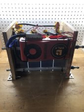
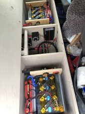
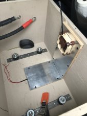
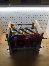
I see you're one of the few, like me, doing 17s. I've got the Schneider xw6848. Got a BMS JKBMS with up to 24s inputs.I am doing a 2P17S pack and I am using a 1/16 inch by 1 inch wide spacer on the edge of each cell in my pack. I am making custom buss bars so I don't stress the cell posts. Then I am clamping each column of 10 cells. the short column of 4 cells gives me room for my BMS, contactor and fuse in my cabinet. My cells will be on their sides in a cabinet on a wall next to my inverter.
Good job
I would not even put cells on flat sides. Search YouTubeI am doing a 2P17S pack and I am using a 1/16 inch by 1 inch wide spacer on the edge of each cell in my pack. I am making custom buss bars so I don't stress the cell posts. Then I am clamping each column of 10 cells. the short column of 4 cells gives me room for my BMS, contactor and fuse in my cabinet. My cells will be on their sides in a cabinet on a wall next to my inverter.
RCinFLA
Solar Wizard
- Joined
- Jun 21, 2020
- Messages
- 3,574
17s LPF puts a 48v inverter at higher risk of damage when DC input overvoltage ringing happens from load surge currents and battery cable inductance. Taping battery pos/neg cables close together reduces battery cable series inductance.
-----------------------------------------------------------
Most metal can LFP cells use the metal case as the battery seal. The top of the actual cell pouch laminates is open to pass electrode collector metal foil to cell terminals and open top end of packet vent gases into metal can. It is the sides of the metal can that bloat from gas pressure. The actual open ended cell packet does not bloat.
When placed on side the open end may allow some excess electrolyte to leak out into sealed metal container, but it does not really do any damage as the electrolyte is saturated in electrode material/separator and does not freely leak out. Only electrolyte that leaks into metal can container area is left over excess from manufacturing fill process done under vacuum to ensure electrolyte is sucked into layers of cell. Any excess spillage into metal casing probably already has happened during shipping.
It is important that casing remain sealed for two main reasons. Electrolyte solvent will evaporate if open to air and mixing water vapor in air with lithium is bad since lithium is very reactive with water.
Attachments
Ampster
Renewable Energy Hobbyist
Thanks for the input. I ultimately reached the same conclusion as @Itohmamma and @RCinFLA . I now have a 3P16S pack in two rows with thin plastic separators between the cells and compression with thread rod. They are in the traditional configuration with the vents at the top.
Last edited:
Do not lay prismatic cells on their sides!17s LPF puts a 48v inverter at higher risk of damage when DC input overvoltage ringing happens from load surge currents and battery cable inductance. Taping battery pos/neg cables close together reduces battery cable series inductance.
-----------------------------------------------------------
Most metal can LFP cells use the metal case as the battery seal. The top of the actual cell pouch laminates is open to pass electrode collector metal foil to cell terminals and open top end of packet vent gases into metal can. It is the sides of the metal can that bloat from gas pressure. The actual open ended cell packet does not bloat.
When placed on side the open end may allow some excess electrolyte to leak out into sealed metal container, but it does not really do any damage as the electrolyte is saturated in electrode material/separator and does not freely leak out. Only electrolyte that leaks into metal can container area is left over excess from manufacturing fill process done under vacuum to ensure electrolyte is sucked into layers of cell. Any excess spillage into metal casing probably already has happened during shipping.
It is important that casing remain sealed for two main reasons. Electrolyte solvent will evaporate if open to air and mixing water vapor in air with lithium is bad since lithium is very reactive with water.
Ampster
Renewable Energy Hobbyist
I actually got the idea to lay them flat from a YouTube video. I have since changed the configuration a year ago when I added more cells and moved the whole system to another home.Do not lay prismatic cells on their sides
Last edited:
Reading through the different threads on the topic of cell compression there seems to be three camps. Fixed compression, compression with springs and compression using foam.
Has anybody actually measured the increase in force when using fixed compression when cycling SOC ?
While I understand that some want perfection and want to try to hit as close to 300 kgf as possible throughout the discharge and charge cycles, but based on cycle life as function of pressure it does not seem to be that important as long as it is in the 150-400 kgf range. Lower than this being not critical, but higher than this potentially causing damage to cell casing.
Having rigid fixed 300 kgf force applied on less than full SOC does seem a bit excessive as I suspect that the expansion of the cells will cause the pressure to increase quit a bit beyond 300 kgf when charged to full SOC, especially when taking thermal expansion into account.
However 0.5 - 1 mm expansion on each cell is not a lot, maybe this is taken up by the casing of the cells acting as a spring as well ?
Bob B
Emperor Of Solar
- Joined
- Sep 21, 2019
- Messages
- 9,465
I doubt that anyone taking the snug it up and it's good to go approach is going to take the time to do pressure readings at various SOC.Reading through the different threads on the topic of cell compression there seems to be three camps. Fixed compression, compression with springs and compression using foam.
Has anybody actually measured the increase in force when using fixed compression when cycling SOC ?
While I understand that some want perfection and want to try to hit as close to 300 kgf as possible throughout the discharge and charge cycles, but based on cycle life as function of pressure it does not seem to be that important as long as it is in the 150-400 kgf range. Lower than this being not critical, but higher than this potentially causing damage to cell casing.
Having rigid fixed 300 kgf force applied on less than full SOC does seem a bit excessive as I suspect that the expansion of the cells will cause the pressure to increase quit a bit beyond 300 kgf when charged to full SOC, especially when taking thermal expansion into account.
However 0.5 - 1 mm expansion on each cell is not a lot, maybe this is taken up by the casing of the cells acting as a spring as well ?
Well that is a fair point. If you worry about these things then it is quick and easy in most of the world to just add a couple of springs just in case.
Die springs are however not that easy/cheap to get hold of in some parts of the world, like for example where I am from in Scandinavia.
I do however suspect that springs might not really be needed due to the small amount of required deflection and the convex nature of the cell expansion. Especially if using wood endplates and 4S/8S configurations. Wood is not super stiff.
The reason that I ask is that this seems to be the main unanswered question in these threads.
I have some pressure load cells and can do such a test, but just trying to figure out if this is something that it is worth my time to spend time on.
Sadly i don't think i have the equipment to measure deflection, but should be able to measure force.
Ampster
Renewable Energy Hobbyist
I am in the snug it up camp. I have previously over discharged Leaf modules and Thundersky prismatics and seen the result of internal pressure as the cells fan out putting strain on bus bars. Snug works for me on my 3P16S pack of EVE 280 cells.
Yurtdweller
Solar Enthusiast
I'm currently running two 12v packs of lf280k at low C rates. This is a 560ah bank. 70a charging, rare occasions of 100a discharging. I have them currently capton taped and bound in milk crates with mega zip ties. I have noticed no expansion of any sort at any time. I have one pack that I built with 2x10 wood plates and all-thread compression screws, but I'll admit that I'm not currently using this particular pack. I also purchased a 100ah LiFePo4 pack from lynx systems on Amazon, and it arrived with a single zip tie holding it together. I never had any problems with it when it was my only battery. I am about to build a crate to hold all four of my 280ah packs, and I plan to leave at least one inch clearance around the outside of the packs, but I am not spacing my cells, other than having 1mm HDPE separators between cells. I've never noticed my cells warming at all.
Yeah. With rigid busbars you kind of either need to snug them up well or have long enough busbars to be able to space them enough to let them expand and contract naturally without causing poor contact to the busbars.I am in the snug it up camp. I have previously over discharged Leaf modules and Thundersky prismatics and seen the result of internal pressure as the cells fan out putting strain on bus bars. Snug works for me on my 3P16S pack of EVE 280 cells.
I plan to run fairly high C rates with several cycles every day. I therefore think I kind of need some kind of pressure to prevent delamination internally in the cells.
But then again, cell compression does harm cooling as well.
For EVE LF280K:
At 0.5 C, each cell can create up to 5 W of heating from the internal resistance. That is 80 W for 16S.
At 1 C, each cell can create up to 20 W of heating from the internal resistance. That is 320 W for 16 S.
Real numbers will likely be lower, these are worst case numbers, but they do not include the busbar heating.
For high C rates, cooling becomes as much of a issue as the compression.
It might be that the cell cycle life would actually be higher without any compression as space between each cell will allow the cells to run quite a bit colder for a given airflow.
Running close to 1 C would definitively require a form for active cooling such as fans moving a decent amount of air. To be honest, looking at these numbers i would probably like to have a fan cooling the cells for continuous 0.5 C operation as well.
S Davis
Solar Addict
- Joined
- Sep 25, 2021
- Messages
- 814
I suspended my cells and am heating/cooling the air around the cells, My two 12 volt 280ah batteries are in a mobile application so needed to be secured well so I clamped them with 160lb die springs.Yeah. With rigid busbars you kind of either need to snug them up well or have long enough busbars to be able to space them enough to let them expand and contract naturally without causing poor contact to the busbars.
I plan to run fairly high C rates with several cycles every day. I therefore think I kind of need some kind of pressure to prevent delamination internally in the cells.
But then again, cell compression does harm cooling as well.
For EVE LF280K:
At 0.5 C, each cell can create up to 5 W of heating from the internal resistance. That is 80 W for 16S.
At 1 C, each cell can create up to 20 W of heating from the internal resistance. That is 320 W for 16 S.
Real numbers will likely be lower, these are worst case numbers, but they do not include the busbar heating.
For high C rates, cooling becomes as much of a issue as the compression.
It might be that the cell cycle life would actually be higher without any compression as space between each cell will allow the cells to run quite a bit colder for a given airflow.
Running close to 1 C would definitively require a form for active cooling such as fans moving a decent amount of air. To be honest, looking at these numbers i would probably like to have a fan cooling the cells for continuous 0.5 C operation as well.
It was only $30.00 more for the springs. I will be running high C rates with a 3000 watt inverter and 150 amp charging. I can see the expansion and contraction of the cells in the length of the springs, if going with a ridged fixture I would be worried about too much pressure at 100% soc.
Attachments
This is doubtful, or the manufacturer would not make a big deal out of specifying compression on the data sheet. The issue is that swelling add contracting allow the electrolyte to migrate. Compression helps keep it where it belongs so the cell doesn't short or lose capacity due to electrolyte loss between the electrodes in specific areas.
How much warmer does your 320 watts make the batteries in an hour? It turns out to be maybe a few degrees. After an hour, the batteries are done (at 1C discharge). If you plan to run high current a lot, cooling might be an issue to you, but compression isn't a trade for cooling. So both if you need them.
How much warmer does your 320 watts make the batteries in an hour? It turns out to be maybe a few degrees. After an hour, the batteries are done (at 1C discharge). If you plan to run high current a lot, cooling might be an issue to you, but compression isn't a trade for cooling. So both if you need them.
This is doubtful, or the manufacturer would not make a big deal out of specifying compression on the data sheet. The issue is that swelling add contracting allow the electrolyte to migrate. Compression helps keep it where it belongs so the cell doesn't short or lose capacity due to electrolyte loss between the electrodes in specific areas.
How much warmer does your 320 watts make the batteries in an hour? It turns out to be maybe a few degrees. After an hour, the batteries are done (at 1C discharge). If you plan to run high current a lot, cooling might be an issue to you, but compression isn't a trade for cooling. So both if you need them.
320 W is a lot of heat. Just look at the amount of fans and heatsink necessary on a modern high end gaming graphics card, that has similar heat output. Yes there are more thermal mass, but in my application I also would go directly from discharge to high C charging. To put things into context i am building a diesel hybrid system with a large 30 kW diesel generator and a 10 kW inverter. The purpose of the batteries is to lower the required runtime for the diesel generator. Current will always run into or out from the batteries. There is no time for them to cool off.
Similar threads
- Replies
- 31
- Views
- 3K
- Replies
- 44
- Views
- 4K
- Replies
- 20
- Views
- 1K
- Replies
- 1
- Views
- 477
- Replies
- 9
- Views
- 722