diy solar

diy solar

Signature Solar EG4 6.5K Off-Grid Inverter | 6500EX-48

Ian at Watts247 showed the LV6548 running only on PV and powering multiple shop tools like chopsaw, tablesaw. There is a Youtube video if you want to see it.
Yes, thank you. This was the video that gave me the assumption that I could run this unit batteryless. I see in this video he does not connect to the grid and he does not mention any settings on the inverter.. It seems that it could be possible to run this batteryless.
 
View attachment 96017
I thought it was UL listed then while editing the video I found out it was TUV listed. Which Ian from watts24/7 told me couple days later is what the lv6548 had all along. Signature solar told me that the screw terminals for mc4 allows it to pass inspection. But Ian said the first lv6548 has passed inspection "hundreds of times". So I don't know what to think right now. Pretty annoyed by it all. Worked hard on those stupid videos and this happens.

Probably need to make sol ark videos and just get people to spend 3X as much so this issue just stops. Why can't the companies get this thing UL listed instead.
A Sol Ark 15k video would be sweet
 
This is to avoid ground loops that might cause RFI issues.

You could do this as well.

View attachment 96473


This works fine and as far as I know, is to code However there are a lot more connections in the ground path to the critical loads box. I like to try to minimize the connections between any one point and the main grounding spot...... (Yes, my anal-retentive nature is showing :))
Thanks again..

Since the two indoor panels would be right next to each other, it wouldn't be difficult to run a ground wire to the sub panel from the crit panel to match your original schematic. I'm moving hots and neutrals anyways, so one more wire shouldn't be a problem. What gauge wire would be sufficient for this? Guess I'll just have to run two 6 gauge wires from inverter output to the crit box.

You said the second version would cause a ground loop which might cause radio interference issues, is that the worst problem? What are you talking about here? Is there a safety issue also?
 
Last edited:
You said the second version would cause a ground loop which might cause radio interference issues, is that the worst problem? What are you talking about here? Is there a safety issue also?
I think the second one creates a lot more connections between the critical load panel and the central grounding point in the main box.
This is not a ground loop and is perfectly legit. I just like to minimize the connections between points on the EGC system. (Star configuration vs daisy chain config)
 
Double check your current setup, I'm fairly confident you will only be feeding one side of your main panel buss bar if you wire up as planned... you should have 2 hots, L1 and L2, going to your main panel from your meter panel.
I don't think I understand what you're trying to say. There are two hots going from the pole panel (or meter panel you're referring to?) going into the house sub panel. I am using one of the hots (L1 or L2) for the inverter input , but not both.

I just wanted to know if it mattered if I plugged the 60A breaker for the inverter to the outside service pole panel or the inside sub panel. Apparently it doesn't matter, but I wanted to be sure.
 
Last edited:
I think the second one creates a lot more connections between the critical load panel and the central grounding point in the main box.
This is not a ground loop and is perfectly legit. I just like to minimize the connections between points on the EGC system. (Star configuration vs daisy chain config)
Ok, makes sense. Would the 6 gauge wire I'm using for the hot and neutral inverter inputs and outputs be sufficient for this ground wire?

One more question, and I'll leave you alone (until tomorrow. Maybe). I'm thinking of mounting the inverter on a wall in the closet of the room these panels are (and will be) located. Is it to code to just run the output wires from the inverter down thru conduit, along the floor of the room, and up to the crit load box? Is it also legal to run the input wires to the inverter thru the same conduit? And what size and material (pvc or metal) conduit would be sufficient for either situation?

Thank you. You should be getting some consultation fees with all these questions from all of us! Oops..
 
Ok, makes sense. Would the 6 gauge wire I'm using for the hot and neutral inverter inputs and outputs be sufficient for this ground wire?
Yes

along the floor of the room,
Are you saying across the floor or along the baseboard? Across the floor would be a trip hazard and might violate some of the pannel access requirements. I don't know of anything that would prevent you from going along the baseboard.

Is it also legal to run the input wires to the inverter thru the same conduit?
I don't see a problem with it, but when running more than 2 conducting wires through a conduit, there are some degrading rules on the wire (the wire is supposed to be larger). (Note that the ground wire is not conducting). Every time I run into it I have to go look it up to figure out how to do the derating.

And what size and material (pvc or metal) conduit would be sufficient for either situation?

You would need to look up a conduit fill chart.
 
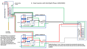
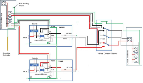
Folks, I put together drawings showing the grounding and bonding of the MPP LV6548 and EG4 6500EX-48 for several different scenarios.

Please let me know if you see any errors.
Appreciate the diagrams. Basically confirms my thinking on a 2 unit OFF GRID only install.

Not necessary, but a diagram for a 2 unit OFF GRID with generator might be useful. Either via manual transfer switch or AGS from the inverter.

Also, just curious. In a dual inverter setup, can you have AC input going into just ONE of the inverters (120) so it can still charge the batteries if needed, or would you need a 240v generator? I'm guessing it would be in imbalance in the system, but who knows .. while one inverter is charging the batteries, the other can be using them to provide the full 240.

Roy
The short answer is "I don't know".

The long answer is that it would work as long as 1) there is a setting someplace that never let the inverters go into pass-through mode and 2) the inverter is able to charge when in inverter mode.
 
Yes


Are you saying across the floor or along the baseboard? Across the floor would be a trip hazard and might violate some of the pannel access requirements. I don't know of anything that would prevent you from going along the baseboard.


I don't see a problem with it, but when running more than 2 conducting wires through a conduit, there are some degrading rules on the wire (the wire is supposed to be larger). (Note that the ground wire is not conducting). Every time I run into it I have to go look it up to figure out how to do the derating.


You would need to look up a conduit fill chart.
Baseboard only. It'd be on the same wall, so no need to cross the floor.

Distance from inverter to panels would be about 20-25 ft. Does the wire sizes have to be increased because there would current flowing in opposite directions in close proximity, and therefore cause some canceling effect?
 
The short answer is "I don't know".

The long answer is that it would work as long as 1) there is a setting someplace that never let the inverters go into pass-through mode and 2) the inverter is able to charge when in inverter mode.
Fair enough. I am building up my battery bank big enough so I don't need a backup generator anyway. Enough battery power for 3 "normal use, no solar" days, and 5 "normal use, cloudy" days. If I need a generator past that then I'll just charge the battery banks "offline".

At least thats the plan.
 
Not necessary, but a diagram for a 2 unit OFF GRID with generator might be useful. Either via manual transfer switch or AGS from the inverter.
I thought about that but decided I had to stop somewhere. (The possible scenarios are numerous).

A two-unit split-phase system would require a generator with split-phase output. That is starting to get into a higher-end install and will be a bit less common than the other scenarios. I am pretty burnt out on this today..... maybe I'll add it another time.
 
Baseboard only. It'd be on the same wall, so no need to cross the floor.

Distance from inverter to panels would be about 20-25 ft. Does the wire sizes have to be increased because there would current flowing in opposite directions in close proximity, and therefore cause some canceling effect?
No, It has to do with heating. Even properly sized wires generate heat and the conduit holds the heat. In order to make sure this is not a problem, they require larger wires that generate less heat.
 
Not necessary, but a diagram for a 2 unit OFF GRID with generator might be useful. Either via manual transfer switch or AGS from the inverter.
OK.... I went ahead and added it. (It was bugging me after you asked) I realized that a split-phase generator, it is just as likely to have an internal bond as not. You would treat those cases differently so I ended up doing two different scenarios. One with a bonded generator and one without.

Note that if the generator is properly sized to the system, it is going to be a 15KW or more generator..... Not a lot of people have something like that. Most people with that size generator are probably going to hire someone to design and install the system.
 
Ok, solar newbie question, instead of disabling the n-g screw inside the inverter panel and possibly voiding the warranty, Is there any other way to disable the n-g bond ?
 
Ok, solar newbie question, instead of disabling the n-g screw inside the inverter panel and possibly voiding the warranty, Is there any other way to disable the n-g bond ?
Yeah, DON'T! I think we've beaten it to death in this thread that it is not necessary under any circumstances and risks ground fault failure.
 
So you are saying to NOT use this diagram provided by FilterGuy of a two-unit setup running split-phase with AC connected that removes one of the bonding screws?. Here we go again searching for the correct way to wire these. I'll just use this diagram as written. PS, I already have this transfer panel installed, a Generac 5449 from a generator backup that these inverters will be connected to. The wire from the 5449 Generac panel has 2224 sec cable coming from it, dropped down to #6 that was connected to a 50A generator receptacle wired for 100amp, 24 K generator that was never installed. The wires going to the critical load box in the below picture will be connected as below then, I hope. https://www.nationwidegenerators.com/content/5449 Spec Sheet.pdf

1653998977715.png
 
Last edited:
So let me get this straight. If I get a single 6500EX, wired into a reliance transfer switch (like the 310C) I would have no issues with grounding correct? How about if I get two 6500EX, operating in split phase mode and using the same Reliance transfer switch and no AC input to the inverter will there be an issue there and how would I resolve it? Thanks.
 
So you are saying to NOT use this diagram provided by FilterGuy of a two-unit setup running split-phase with AC connected that removes one of the bonding screws?. Here we go again searching for the correct way to wire these. I'll just use this diagram as written. PS, I already have this transfer panel installed, a Generac 5449 from a generator backup that these inverters will be connected to, I hope.

View attachment 96523
Please read my earlier posts, here and here. There is no need to void your warranty to make this unit work. The issue is NOT a problem when the wiring is sized properly and all of the connections are secure. I appreciate what FilterGuy is trying to do, but IMO he should not advise people to void their warranty just because he doesn't like the way it's designed. There is no code violation or safety concern, and there is a greater chance of blowing up your inverters if you remove the screw and then a ground fault occurs in the system. "The electrons have nowhere to go."
Also, Will tried it with just 1 ground screw removed and it didn't work, he said. He removed both screws and grounded it at the sub-panel, and that worked BUT he now has 2 N-G bonds when the inverter is bypassed. There was no need to do this!

Just follow the manufacturer's instructions and size your wire and ground wires properly, and put your wires in grounded metal conduits or wire troughs to shield the RFI. There is no issue with current flowing between the two inverters along the ground wires, it doesn't hurt anything or anyone.
 
Last edited:
  • Like
Reactions: Zwy
So let me get this straight. If I get a single 6500EX, wired into a reliance transfer switch (like the 310C) I would have no issues with grounding correct? How about if I get two 6500EX, operating in split phase mode and using the same Reliance transfer switch and no AC input to the inverter will there be an issue there and how would I resolve it? Thanks.
If the AC from the mains is going to the switch and not through the 2 inverters, and the inverters are properly grounded with properly sized wires. Then there is no issue at all.
If the AC from the mains is going through the inverters, then you don't need the extra transfer switch and there is still no issue. The transfer switch is an unnecessary expense.
 
@FilterGuy, here are my redlines and suggestions for your document. No offense intended, just trying to contribute with my own NEC expertise and experience. Peace!
 

Attachments

  • REDLINES_Grounding lv6548 and 6500EX-48.pdf
    1 MB · Views: 52
If the AC from the mains is going to the switch and not through the 2 inverters, and the inverters are properly grounded with properly sized wires. Then there is no issue at all.
If the AC from the mains is going through the inverters, then you don't need the extra transfer switch and there is still no issue. The transfer switch is an unnecessary expense.
Reason I am asking is because I would like to be confident I am purchasing something that's not going to cause me problems. I do appreciate you taking time to respond, however, if there's no issue, what is all this discussion about?
 

diy solar

diy solar
Back
Top