diy solar

diy solar

Signature Solar EG4 6.5K Off-Grid Inverter | 6500EX-48

Yes. That is what he is saying. He and I are of different opinions about whether multiple NG bonds are an issue.

The fact is, the system will work with multiple NG bonds, but 1) it creates undesirable current on the grounds and 2) it creates an unsafe situation during servicing. (This is why you never generate an NG bond in a sub-panel)
I don't see why anyone would think that these inverters are hot-swappable, so point 2 is a non-issue. If you need to service it, you must turn the power off to all the inverters on the circuit, or have an isolation switch on every inverter. That depends on if you are just powering your home or if you're powering a critical load that can't be interrupted. My home is not that critical, I have a UPS on my computer.

There are plenty of transformers, electric motors, and appliances that have high leakage current on the ground wire, in excess of 5A. This is a normal operation for these items and they are all UL or CSA or TUV certified. The only time leakage current on the ground wire must be prevented is for Medical equipment. Back in the 1990's I was designing UPS and XFMR's for Medical use and we had to get the leakage current below 4uA or some minuscule number like that. Double copper shielding between primary and secondary, extra Nomex paper between them to reduce capacitive coupling, etc.

The EG4 inverters are not specified for Medical use. Please, stop worrying people about ground currents. It's not an issue if your ground wires are sized to handle a fault current and have solid connections. It's a non-issue that is worrying a lot of people for no good reason. Thank you!
 
There is nothing in the NEC code that says current can't flow through a ground wire. I've been dealing with the NEC since 2006. In fact, in the US there are many old houses that use the metal conduit as the grounded neutral conductor, and others where there is only 1 grounded conductor, running throughout the entire building. Current flowing in a ground wire is only a problem if there is a poor connection that allows that current to turn into a voltage potential relative to ground. Good solid connections and properly sized wires avoid this concern, so there is no problem.

Just FYI: I'm Todd Desiato, a degreed Engineer who has been designing solar inverters since the 1980s and designing residential, commercial and utility-scale solar systems since 2010. I've gotten multiple permits and passed inspections in LADWP territory, one of the hardest places in the country to pass inspection, and all up and down the east and west coast. I don't claim to know everything in the NEC code, but I know solar inverters inside and out.
So this is an ok circuit with multiple NG bonds?

1654014789614.png
 
Just FYI: The original 24kW REFUSol 3-phase string inverters would not run reliably unless we put an N-G bond at every inverter in the field. We had 44 of them! Long wires and interference were enough to cause them to mistakenly detect ground faults that weren't there and shut down randomly. Point: Multiple N-G bonds is not unheard of in solar, or in modular inverter design, or on distributed generation grids
 
I don't think I understand what you're trying to say. There are two hots going from the pole panel (or meter panel you're referring to?) going into the house sub panel. I am using one of the hots (L1 or L2) for the inverter input , but not both.

I just wanted to know if it mattered if I plugged the 60A breaker for the inverter to the outside service pole panel or the inside sub panel. Apparently it doesn't matter, but I wanted to be sure.
Sorry I was tired, shouldn't have been replying to posts...
If you only use one inverter on L1 or L2 wouldn't you still be feeding half your panel with utility power?
I suppose using the single inverter would work if you don't have any double pole breakers in the house panel. If you have any double pole breakers in the panel you would be feeding one leg with the utility and one with the inverter; I assume this would be bad.
My current wiring is very similar to yours, power from the meter connects to a main 200a single disconnect on the inside wall, this then runs across the basement through the floor to the main panel, my main panel also feeds a subpanel. I will be using 2 inverters, if I go with the EG4, to feed both legs.
 
So this is an ok circuit with multiple NG bonds?

View attachment 96548
Yes, there is no code violation as long as both connections are sized to handle the full fault current.
If you needed to run 2000 MCM for the ampacity, wouldn't you choose to use 4 x 500 MCM wires, rather than handle a 2000 MCM cable? Parallel runs are used everywhere in solar. It's no big deal and no inspector I've met has ever said anything about it. My system has this, but my two panels are literally 6" apart. No issues whatsoever.
National Grid utility in MA bonds their N-G at multiple places along the N run from the transformer to the load. That's how they avoid Neutral GPR events, by making sure everything is at the same ground potential along the entire run. (GPR Ground Potential Rise)
 
Just to be clear, there is no issue with multiple N-G bonds PROVIDED they are not separated by great distances where you could have a fault at one location that causes a GPR resulting in two nearby objects having different ground potentials on their chassis. In the case of these EG4 inverters, they are not a great distance apart, and they are close enough that the low-Z bond is not going to allow a large GPR between them. They may as well be in one chassis, it would be the same thing and then this connection/current would be invisible to the end-user.
 
Just to be clear, there is no issue with multiple N-G bonds PROVIDED they are not separated by great distances where you could have a fault at one location that causes a GPR resulting in two nearby objects having different ground potentials on their chassis. In the case of these EG4 inverters, they are not a great distance apart, and they are close enough that the low-Z bond is not going to allow a large GPR between them. They may as well be in one chassis, it would be the same thing and then this connection/current would be invisible to the end-user.
 
Sorry I was tired, shouldn't have been replying to posts...
If you only use one inverter on L1 or L2 wouldn't you still be feeding half your panel with utility power?
I suppose using the single inverter would work if you don't have any double pole breakers in the house panel. If you have any double pole breakers in the panel you would be feeding one leg with the utility and one with the inverter; I assume this would be bad.
My current wiring is very similar to yours, power from the meter connects to a main 200a single disconnect on the inside wall, this then runs across the basement through the floor to the main panel, my main panel also feeds a subpanel. I will be using 2 inverters, if I go with the EG4, to feed both legs.
I think I get at what you're trying to convey.

I'm hooking a 60A single pole CB into the house panel (sub panel), and running the wires from that to the (only one) inverter input. The inverter output is feeding a critical load sub panel, which will have another single pole 60A CB at its input. I probably would have to place the breakers in alternative slots to use the same hot buss in that panel. I'm not feeding back to the main panel other than a ground wire, which @FilterGuy suggested to reduce emissions problems.

None of my critical loads use double pole breakers, they're either 15 or 20A single pole. I'm pulling all those out of the house panel, along with their hot and neutrals and moving them to the crit loads panel. They would be fed by the one hot buss from the inverter. Yes, there are maybe six double pole breakers in the house panel using both L1 and L2, but I'm not moving those or hooking those to the inverter output.

This setup was to switch all of my 120V devices to the inverter output, but still use the grid if the batts/solar can't power them. The higher power 240V devices will stay on the house panel powered by the grid regardless.

I think my setup would work, but that's why I'm asking all these questions. If there's something wrong with it, then I welcome any suggestions.
 
Last edited:
Just to be clear, there is no issue with multiple N-G bonds PROVIDED they are not separated by great distances where you could have a fault at one location that causes a GPR resulting in two nearby objects having different ground potentials on their chassis. In the case of these EG4 inverters, they are not a great distance apart, and they are close enough that the low-Z bond is not going to allow a large GPR between them. They may as well be in one chassis, it would be the same thing and then this connection/current would be invisible to the end-user.
I guess we just have to agree to disagree and move on.
 
Yes, there is no code violation as long as both connections are sized to handle the full fault current.
If you needed to run 2000 MCM for the ampacity, wouldn't you choose to use 4 x 500 MCM wires, rather than handle a 2000 MCM cable? Parallel runs are used everywhere in solar. It's no big deal and no inspector I've met has ever said anything about it. My system has this, but my two panels are literally 6" apart. No issues whatsoever.
National Grid utility in MA bonds their N-G at multiple places along the N run from the transformer to the load. That's how they avoid Neutral GPR events, by making sure everything is at the same ground potential along the entire run. (GPR Ground Potential Rise)
And than the plumber arrives, changes the dated water ground system without ever touching any of the electrical , and has no idea about electrical, thus turning the ground current into something potentially dangerous....this scenario is possible and has happened I'm sure many times. Then the electrician is called to probably just drive a proper ground rod in, but again I believe there are reasons that go beyond multiple layers of safety why the goal is to achieve a single NG bond , whether at the power source or breaker box.
 
The reliance 310C does not switch neutral. That means the inverter input neutral ends up being connected to the inverter output neutral. I have heard mixed reports on whether that works with these inverters and we have not had a statement from the manufacturer that it is supported.
(This is why I only show transfer switches that switch neutral in my diagrams)
Well I have been running an AC200P with reliance transfer switch for more than a year now. I simply use the double pole breakers in single pole mode and it's used for circuits from both legs in 120v mode only and I haven't had an issue. How would this differ from the use case I described? What is the significance of the transfer switch not switching the neutral?
 
Well I have been running an AC200P with reliance transfer switch for more than a year now. I simply use the double pole breakers in single pole mode and it's used for circuits from both legs in 120v mode only and I haven't had an issue. How would this differ from the use case I described? What is the significance of the transfer switch not switching the neutral?
When the neutral is not switched, the inverter input and output neutrals are tied together. (See purple dashed line below)

1654021727742.png

The next question is whether that is a problem.... and that is not as clear. People have done this and it appears to work.

However:
* That creates multiple N-G bonds when in inverter mode unless you remove the bonding screw.

* That creates a loop on the neutral when in pass-through mode. (This is not too bad because the inverter is not creating a lot of noise when in pass through mode.)

* We have never received confirmation from MPP or EG4 that this is supported.

1654022125017.png
 
NEC 250.6 doesn't apply for a configuration that has been tested to UL1741 and certified for that purpose, even if it was done by TUV and not UL.
The NEC articles I think are applicable are 250.24 (Dual-Fed Services), para. (5)(C). Also, 250.30(6) Multiple Separately Derived Systems.

This drawing shows how to do it using a JB to enclose any "objectionable currents" between the multiple separately derived systems. Unbalanced loads are a reality, they can't be avoided. Grouping the inverters and considering them to be ONE unit is IMO, perfectly satisfactory.

Screen Shot 2022-05-31 at 2.41.52 PM.png
 

Attachments

  • Screen Shot 2022-05-31 at 2.41.52 PM.png
    Screen Shot 2022-05-31 at 2.41.52 PM.png
    1.6 MB · Views: 39
Last edited:
And than the plumber arrives, changes the dated water ground system without ever touching any of the electrical , and has no idea about electrical, thus turning the ground current into something potentially dangerous....this scenario is possible and has happened I'm sure many times. Then the electrician is called to probably just drive a proper ground rod in, but again I believe there are reasons that go beyond multiple layers of safety why the goal is to achieve a single NG bond , whether at the power source or breaker box.
But it is not possible when using more than one of these types of inverters, split-phase or in parallel. IMO, this is how TUV tested it to UL1741, so as long as you use it per the manufacturer's directions, it's fine. If it bothers you for no reason, use an AIMS LF inverter or a 240V inverter with a split-phase transformer. A split-phase configuration can't be done any other way with a 120V inverter. That's just the way it is.
Another alternative is to get a 120V to 120/240V split-phase isolation transformer. Then you have a new separately derived neutral to bond at your sub-panel that is isolated from the main panel.
 
If I am following you correctly, we are talking about two separate systems in the same house:

View attachment 96483

This is probably just fine and there are no ground loops. However, since they are both in the same house I *think* the proper way to do it would be to combine the two Equipment Grounding Conductor systems either at the main panel or the grounding electrode for the main panel.
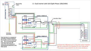
View attachment 96484

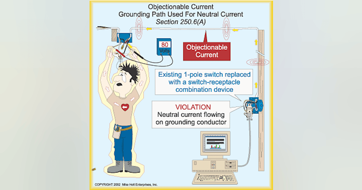
The reason for this is that if there is a nearby lightning strike and there are separate grounding systems with separate grounding electrodes, a very large potential could develop between the two systems. If someone happens to be touching something grounded by the grid system and something grounded by the off-grid system, they could be zapped.
I am grateful for your responses and time.

I was less than clear about the situation. There will two separate systems at the same house. Currently, one is a standard residential 240 split phase service panel that feeds my house. The solar system is intended to be an off-grid source of power during grid outages that will feed a non-grid connected mini-split heat-pump and enable connection of 12 AWG extension cables to run a freezer, refrigerator, and a few lights in case the grid goes down.

An EG4 6548 EX inverter and EG4 5.1kV battery will be delivered 2022-06-01. I was going to connect my main service panel's AC into the EG4 6548 EX via a 125A sub-panel for AC into the inverter. From what I understand, to avoid more than one N-G bond in the house's electric system the inverter's N-G bond screw would have to be removed in order to enable grounding the inverter via the AC input fed from the main service panel.

Unfortunately, there appears to be no feasible code-compliant/permittable way to connect an off-grid inverter that is not UL Listed to a sub-panel connected to a main service panel. In order to have a legal installation in my area, a UL listed off-grid inverter must be installed by a licensed electrician and the installation must meet National Electric and International Construction Codes. Currently, the EG4 6548 EX inverter is not UL Listed. In my area, without UL listing, an inverter will not be permitted to be connected to the grid via a sub-panel.

Upon the realization that my original plan was not feasible, my thought was to run an Equipment Grounding Conductor (EGC) from the ground of the inverter's AC output panel back to the main service panel. To avoid multiple N-G bond points, the inverter's AC output panel would not bond neutral to ground but would instead be bonded back at the main service panel via the EGC run from the ground terminal in the sub-panel.

To make sure I have only one N-G in the system, I was going to remove the N-G bond screw in the inverter as if AC input power from the main service was supplied. I am still not sure if bonding the inverter's AC output panel to the service main ground is allowed by code.

Diagram 2 above is almost exactly what I was thinking with the exception that the diagram shows the N-G bond screw is still connected in the inverter.
Please advise on two questions:
1) if the inverter output AC panel is connected via EGC back to the main service panel's ground bar, should the N-G bond screw in the inverter be removed?
2) Does connecting the EGC to the main panel violate NEC code?

I apologize to the pros on the forum if my thoughts are naive, I am grateful for thoughts on the matter.
 
NEC 250.6 doesn't apply for a configuration that has been tested to UL1741 and certified for that purpose, even if it was done by TUV and not UL.
The NEC articles I think are applicable are 250.24 (Dual-Fed Services), para. (5)(C). Also, 250.30(6) Multiple Separately Derived Systems.

This drawing shows how to do it using a JB to enclose any "objectionable currents" between the multiple separately derived systems. Unbalanced loads are a reality, they can't be avoided. Grouping the inverters and considering them to be ONE unit is IMO, perfectly satisfactory.

View attachment 96565
That drawing has one n-g bond in inverter mode and 1 n-g bond in bypass mode.
That is not a topo that I would have a problem with.
I would have a problem if both AIOs hand N bonded to G.
 
But it is not possible when using more than one of these types of inverters, split-phase or in parallel. IMO, this is how TUV tested it to UL1741, so as long as you use it per the manufacturer's directions, it's fine. If it bothers you for no reason, use an AIMS LF inverter or a 240V inverter with a split-phase transformer. A split-phase configuration can't be done any other way with a 120V inverter. That's just the way it is.
Another alternative is to get a 120V to 120/240V split-phase isolation transformer. Then you have a new separately derived neutral to bond at your sub-panel that is isolated from the main panel.
Yes, I have come to realize some of the few downsides to these units and how they function with relation to the bonding. I also understand that some objectionable current over a short run of or protected and properly sized and grounded conductor will not likely be a risk or danger. I have seen lightning damaging equipment mentioned before but not sure how this would play into this debate.
I understand there are people that want as little and most minimized risk as possible, and I think that is why this is such a sticking point with these inverters. Also the fact that they have much to be desired in terms of documentation. I'm appreciated of the documentation that has been done on this forum and it sure helps the community.
 
That drawing has one n-g bond in inverter mode and 1 n-g bond in bypass mode.
That is not a topo that I would have a problem with.
I would have a problem if both AIOs hand N bonded to G.
Good catch. I knew I was forgetting one more thing I needed to change. It's fixed now. All grounded per UL1741 test certificate, as designed. Honestly I don't care if anyone wants to void their warranty and the TUV safety certification to have it their way. I'm just saying, it's not necessary for any sort of "compliance". It complies just the way it was tested, per the manufacturer's instructions. Testing to a UL standard means any conflict with NEC is over-ridden by the UL standard testing. It was tested for this application, in this configuration and deemed safe by TUV. That's all I or you need to know.
 
Last edited:
When the neutral is not switched, the inverter input and output neutrals are tied together. (See purple dashed line below)
OK, I think I understand the issue now, however as I indicated, in my setup, there's is no AC input whatsoever. It's a manual transfer switch so whenever I wish to use mains power I just flip the switch. Now if I was going to use AC inputs on the inverter, it would make more sense to use the internal transfer switch and eliminate the reliance. And this is where I'm seeing the major disagreements as to whether it's safe with or without the screw. Who is right? I don't know, but I don't want to make an expensive mistake.
 
OK, I think I understand the issue now, however as I indicated, in my setup, there's is no AC input whatsoever. It's a manual transfer switch so whenever I wish to use mains power I just flip the switch. Now if I was going to use AC inputs on the inverter, it would make more sense to use the internal transfer switch and eliminate the reliance. And this is where I'm seeing the major disagreements as to whether it's safe with or without the screw. Who is right? I don't know, but I don't want to make an expensive mistake.
My first inverter design passed UL1741 in 1988, and I was tasked with making sure every inverter we were manufacturing at Topaz, Inc. was ready to pass the standard when it was implemented and made mandatory. I've been doing this stuff for nearly 40 years, and I've been installing solar since 2010 in many major cities. I've been through over 500 permit reviews and inspections, in cities like LA, Santa Cruz, San Diego, Minneapolis, Parsippany, etc.., and I've learned what can and can't be done, per code. I was licensed in CA, but not in NC (yet), I'm ready to retire. What I'm saying is, you can trust what I say and take it to the inspector.
 
An inverter can be tested to UL1741 standard by UL, CSA or ETL and be "Listed", and this is acceptable to any AHJ Inspector I've ever worked with. The EG4 inverter says TUV Certified to UL1741 for compliance. It isn't "Listed" because TUV doesn't use that term. However, they are a Nationally Recognized Testing Laboratory (NRTL) that certifies products, just like UL, CSA and ETL. UL Listing and UL Recognized both fall under the category of "Certified", so there is some ambiguity because of their terminology. Some AHJ's may not be aware that the cTUVus mark is equivalent to a UL Listing when tested to the same standards, but that is changing.

"The cTUVus mark is officially recognized as an equivalent and direct replacement of the UL and CSA marks. UL is both a US standards body and a laboratory. National Recognized Testing Laboratories (NRTL) like TÜV Rheinland can test to the same standards and specifications as those defined by UL as US standards."

Your inverter doesn't need to be tested by "UL" to be acceptable anymore. Other laboratories are competing with UL, which is good because the cost is outrageous to get a product certified these days. The EG4 inverters bear the cTUVus Mark, which is equivalent to a UL Listing mark.

Screen Shot 2022-05-31 at 4.18.15 PM.png
 
If the AC from the mains is going to the switch and not through the 2 inverters, and the inverters are properly grounded with properly sized wires. Then there is no issue at all.
If the AC from the mains is going through the inverters, then you don't need the extra transfer switch and there is still no issue. The transfer switch is an unnecessary expense.
What was acceptable in the past has NO relevance in a new install.

Grounding conductors have two and only two jobs in modern home wiring…

Static and surge dissipation, and overcurrent fault path…

Designing a system using the grounding conductor to carry current is a path to problems, and is against modern codes.
 
However, after seeing these EG4 6500 units, this seems to be the solution to all of that because you can both get 240v service and you can get 120v service without the limits of an auto transformer. Additionally, you seem to be able to use multiple units on each 120v leg to have up to 19500W per 120v leg. Can someone please advise if I have missed something.

That seems to be the idea. I even seem to recall some of these AIOs manuals suggesting that you can stack legs disproportionately within a given range if your 120v needs far exceed your split-phase ones.

Potential downsides include paying extra efficiency costs (generally already higher per-unit), generally lower quality (presumably), more complicated wiring, more space usage.

On the flip side, it's easier to replace parts that fail if they fail one at a time.

This grounding discussion is pretty spicy, though.
 
i have a stupid question, unfortunately..whats the max amps the ac input can handle from utility? Is it the same as pv, 120a?
 
Last edited:

diy solar

diy solar
Back
Top