diy solar

diy solar

Cinergi's 28 kWh / 4 kW Solar / 10 kW inverter RV build

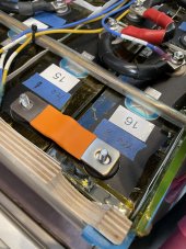
New bus bars installed.

At 17 amps with old bus bars, I saw a 0.3mv drop across the long bus bars. With the new ones, it was 0.5mv. Expected - these aren't nearly as much copper. But I'd have to think they're copper based on how they're performing. I have no concerns there.

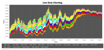
I charged and let the battery balance to 10mv and then drew it down to 93%. I then charged from shore power at max (120 amps at 56 volts, over 6000 watts), and everything remained cold. The Orion BMS cell voltage graph looked excellent and I had no runners as the battery reached full. Orion cell resistances all looked great, too. This was a great initial test - and a good test to make sure my parallel connections were good (otherwise I would have runners). So I'm happy with the bus bars. We'll see how things fare over the next few days and months...
 
On a separate note, it's been over 1 year since I put this into commission. The Orion BMS tracks the total # of pack cycles (a "cycle" is the sum of Ah discharged & charged - 2x the Ah rating - so for me, 1080 Ah on a 540 Ah pack). I never reset that number, so it includes all the testing I did during the build. I'm at 257 cycles. At a 4,000 cycle "lifespan" that's 15 years.

I'm sort of accidentally doing a capacity test now because I'm running the mini-split heat during a cold & rainy period right now. I'm down to 39% and falling. I'm gonna configure the Quattro's to connect to shore just before they shut down due to low voltage, maybe 47 volts (2.94 vpc) and I'll see what the consumed Ah is etc. Hopefully very close to 540 :)
 
New bus bars installed.

At 17 amps with old bus bars, I saw a 0.3mv drop across the long bus bars. With the new ones, it was 0.5mv. Expected - these aren't nearly as much copper. But I'd have to think they're copper based on how they're performing. I have no concerns there.

I charged and let the battery balance to 10mv and then drew it down to 93%. I then charged from shore power at max (120 amps at 56 volts, over 6000 watts), and everything remained cold. The Orion BMS cell voltage graph looked excellent and I had no runners as the battery reached full. Orion cell resistances all looked great, too. This was a great initial test - and a good test to make sure my parallel connections were good (otherwise I would have runners). So I'm happy with the bus bars. We'll see how things fare over the next few days and months...
good going. 120A with minimal heating, sounds satisfyingly like a win for the day.
 
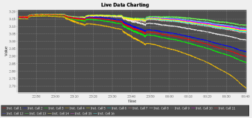
8% - 50.7 volts. Some serious divergence started ... at 60mv now. In theory I should still have another 43Ah left. I doubt I'll get that far. And I don't know that I performed a capacity test using the BMS to measure the Ah so this isn't really apples-to-apples. I tested each cell using a CBA IV tester and my lowest cell was 270 so I set the pack capacity to 540 (since I'm in a 2p config).

1654140104079.png
 
8.4Ah left and I've got a cell-pair below 2.7 volts. Pack voltage is 48.2. I've configured it to connect to shore at 48v. Assuming the BMS calculation is the same as the CBA IV tester I used, I'm at 98.5% of my original capacity (likely higher). I now also know what pack voltage to use for inverter shutdown that will safely keep me away from that particular runner.

This has also had a nice side-effect from a testing standpoint of making my cells contract and expand their maximum amount, putting the new busbars to the test.

1654144835455.png
 
8.4Ah left and I've got a cell-pair below 2.7 volts. Pack voltage is 48.2. I've configured it to connect to shore at 48v. Assuming the BMS calculation is the same as the CBA IV tester I used, I'm at 98.5% of my original capacity (likely higher). I now also know what pack voltage to use for inverter shutdown that will safely keep me away from that particular runner.

This has also had a nice side-effect from a testing standpoint of making my cells contract and expand their maximum amount, putting the new busbars to the test.

View attachment 96882
Any more updates? Curious to hear the final result.
 
Any more updates? Curious to hear the final result.

It connected to shore at around 2.65v (nearly 400mv of deviation - expected, given I have cells that tested to 270Ah and others at 281) so 98.5% (probably higher due to my testing methods here) of my original capacity 1 year ago.
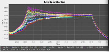
I got it fully charged about an hour ago. 125mv of deviation at the top and it balanced to 10mv in 70 minutes. All cell resistances look great (meaning my new bus bars are holding up despite the contraction & expansion). I disconnected from shore at roughly 19:40 in the graph below.

1654214431418.png
 
Thanks for the data, very useful!

A couple questions, I tried wading through the thread, but gave up after 10 pages. What is your charge voltage? How many months/years has the pack been in service?

The reason I ask, is so that I can work out your degradation a function of pack age and cycles.
 
Thanks for the data, very useful!

A couple questions, I tried wading through the thread, but gave up after 10 pages. What is your charge voltage? How many months/years has the pack been in service?

The reason I ask, is so that I can work out your degradation a function of pack age and cycles.

Absorb *and* float is 56v. I'm generally at that voltage less than 4 hours a day. Pack is just over a year in service. About 260 cycles. It was operating in elevated temps (over 90F) for < 1 month. Temps never got below 40F. Charge amperage max per cell is < 40 amps (.15C). Discharge max is similar.
 
1% per year while cycling is very good, Though your temps aren't southwest like, which helps. Assuming a standard capacity loss acceleration, 15 years should be totally doable, maybe 17 if you don't mind operating with capacity less than 80%.

My vans pack has seen more elevated temperatures, and its been about 18 months, so you may have motivated me to do a capacity test.
 
There's a funny temporary 30mv cell divergence around the 60% SoC mark - always happens whether during charge or discharge. First time I've noticed it (because I've been hanging around 35-70% SoC the past few days due to clouds). Always fine (<5mv) before 60% and fine (<5mv) after roughly 65%. No balancing is occurring at the voltages - it's just an interesting difference in the curve around this spot.

1654557836964.png
 
Just wanted to drop a note to say these busbars are continuing to perform well. I'm so happy I got these. My IR's continue to be amazing and the Orion BMS continues to report that the "State of Health" of the battery is 99% which it never did before (because it saw such variation in the IRs). The pack has cycled down to 15% at least twice since my last report so it's undergone a large amount of movement (remember, I have a spring compression fixture) and everything continues to perform perfectly.
 
Indeed, I empirically proved it's needed in my configuration.
Ho yea, i was pretty sure it was the way to go

I got the same flexible bussbar that you have and very happy with them. :)
 
How much surface area of the terminal are they covering?
I ordered them but for the studded cells I have this seems inadequate :(
859CB75A-AEC1-42DC-B193-2AE6787771CC.jpeg
 
All busbars miss a little surface contact (elongated holes). Hasn't proven to be a problem even when I max out my current draw.
 
Ho yea, i was pretty sure it was the way to go

I got the same flexible bussbar that you have and very happy with them. :)

hehe yeah... the problem that it caused was different than everyone assumed (e.g. flexing the innards of the cell and causing damage) -- but rather causing busbar <-> cell terminal contact failure because the bus bar was sliding around underneath a properly-torqued bolt.
 
Good. I never believed that DC vs. AC somehow needed a braid, or needed a solid busbar.
Connectors. The least reliable component in electrical/electronic systems.
I've always though almost-finger-tight nuts on a single stud per connection was inviting problems. I like positive anti-rotation solutions.
Purple thread locking ? Rated for 7N.m and if you do not put much it's lower. And i would add some security paint for visual safety
 
Thread lock would keep a nut from rotating under vibration, but not resist much external force.
Equipment is normally assembled with multiple bolts/studs, and that provides anti-rotation (e.g. of a wheel on hub.)
A few electrical terminals have multiple bolts, but many, like main lugs on a breaker panel, just have one. The act of torquing screw to secure wire causes lug to turn under stud.

A few welded terminals on LiFePO4 batteries have dual studs. Some battery banks have multiple batteries in parallel, so busbars can't turn (except by multiple batteries moving.) But batteries are heavy and expand, so will try to move in mobile and fixed installations.

Cables off last battery, if tugged on, would rotate and overpower any threadlock. I think it is best they are limber (so thermal expansion doesn't move them) an secured against being moved.

As someone noted, serrated nuts could cause material to deform and settle. I've seen how aluminum cooking pots rub oxide off each other while driving. Connections and parts have to be sufficiently secure they don't move from vibration, or they will loosen. If not something like aluminum with its non-conductive oxide, spring-loaded connections could work. Welded busbars, formed to allow some compliance (the originally intended implementation for these cells) seems good.
 
hehe yeah... the problem that it caused was different than everyone assumed (e.g. flexing the innards of the cell and causing damage) -- but rather causing busbar <-> cell terminal contact failure because the bus bar was sliding around underneath a properly-torqued bolt.
Hooo nice to know, the torque should be something like 7 or 8 N.m if i remember correctly from Eve doc, i can see those nuts been losen by successive expansion/contraction and vibrations. And losen nuts are no good .. :D
An other advantage of flexible bussbars ... ;).
 
Thread lock would keep a nut from rotating under vibration, but not resist much external force.
Equipment is normally assembled with multiple bolts/studs, and that provides anti-rotation (e.g. of a wheel on hub.)
A few electrical terminals have multiple bolts, but many, like main lugs on a breaker panel, just have one. The act of torquing screw to secure wire causes lug to turn under stud.

A few welded terminals on LiFePO4 batteries have dual studs. Some battery banks have multiple batteries in parallel, so busbars can't turn (except by multiple batteries moving.) But batteries are heavy and expand, so will try to move in mobile and fixed installations.

Cables off last battery, if tugged on, would rotate and overpower any threadlock. I think it is best they are limber (so thermal expansion doesn't move them) an secured against being moved.

As someone noted, serrated nuts could cause material to deform and settle. I've seen how aluminum cooking pots rub oxide off each other while driving. Connections and parts have to be sufficiently secure they don't move from vibration, or they will loosen. If not something like aluminum with its non-conductive oxide, spring-loaded connections could work. Welded busbars, formed to allow some compliance (the originally intended implementation for these cells) seems good.
Thread locks comes in different "strenght", if you put red on the whole thread, it will be very hard to disasemble .... like VERY.. :)
I agree with you, one stud poorly prevent rotation, but two successive cells act like 2 studs (if cells are properly constrained) so the problem only arise for first and last conenctors which are both "alone".
I know i've used some red loctite thread lock (just a drop on each) and some security paint to visually see if one nut as gone lose.
 

diy solar

diy solar
Back
Top