diy solar

diy solar

Active balancer, make it smart!?

I don't think using 8 relays is going to give you the results you are expecting. The little 8S Heltec balancer works by comparing the voltages between cell balance leads. It pulls current from higher cells and dumps it to lower cells. If you are disconnecting and connecting the leads to cells, the balancing can't work as intended.

I'm with others here: If you are going to make use of these balancers and try to have them work only at certain voltages, do it based on the overall pack voltage, and use one relay on the RUN pads to turn the thing on or off.
 
I think many of these 12/24V devices have a low voltage tolerance. They are really meant for 12/24V. I have an aTorch bluetooth shunt and it worked for a few minutes before the voltage regulator blew. A quick look at the specs and it could only handle 26V max or something like that. My test battery was higher so smoke was released. Need to be mindful of the large voltage swing for your battery.
Yeah my bench power supply was set for 12v (verified with meter) I also used an M12 battery for another 12v supply it also measured right at 12v.

My only thought was that for the few minutes before it let the smoke out I only had 12v power connected, (nothing connected to sensing leads) maybe it needed both ports connected.

Oh well. I maybe looking into a Victron solution I have 100v15a SCC that might be able to rig the load port to a relay, if I can have it turn on the load port at a certain voltage.
What i was referring to was that some of the victron SCC and inverters have actually a dedicated relay port.
IMG_20220609_213220.jpg
IMG_20220609_212920.jpg
 
I don't think using 8 relays is going to give you the results you are expecting. The little 8S Heltec balancer works by comparing the voltages between cell balance leads. It pulls current from higher cells and dumps it to lower cells. If you are disconnecting and connecting the leads to cells, the balancing can't work as intended.

I'm with others here: If you are going to make use of these balancers and try to have them work only at certain voltages, do it based on the overall pack voltage, and use one relay on the RUN pads to turn the thing on or off.
I do not see why that relay would not work. ... That relay would simply provides a off on switch to every cell (in that case 8 cells), as 8 in between switches through each wire in your wire loom between active balancer and each battery cell. ... 8 relays would allow wires to function as they were before cut and routed through the relays. ... While there is a 9th negative terminal black wire in the active balancer wire loom, IMO no big deal if it is not run through a relay. ... OFF/ON control of relay could be manual, or easily automated with a battery bank voltage monitor. It would be an absolute OFF/ON control for the active balancer. ... just some thoughts about options, and protecting your way more expensive battery cells :+)
 
Last edited:
Interesting to see inexpensive option to Heltec. IMO: Heads Up when you wire these to your way more expensive LiFePO4 cells. On top of Will P's video where his testing smoked a Heltec, there are a couple of stories I ran across in this forum, about a Heltec Active balancer malfunction when no one was there, ... messing up batteries. ... The story that got my attention was about about a Heltec malfunction that had been modified (at that solder joint) to have an off/on switch; and poster said he had malfunction when the the switch was turn to OFF. ... I have a Heltec 5A active balancer here to eventually test on my more iffy at top of charge ... 24v 280Ah battery bank (soon to be one of three 24v battery banks). I am gona connect it to my battery cells through an 8 connect relay I will turn off and on manually, and then put on automated ON @ about > 3.4 cell volts. ... My Two Cents ;+)
That's certainly concerning to hear. Once my customized balancer arrives i will do also some testing concerning the RUN solder bridge as well. Wonder how much current there flows between the two solder points of the RUN bridge. As well if switch is off if there is still current flowing from the battery to the balancer.
 
I do not see why that relay would not work. ... That relay would simply provides a off on switch to every cell (in that case 8 cells), as 8 in between switches through each wire in your wire loom between active balancer and each battery cell. ... 8 relays would allow wires to function as they were before cut and routed through the relays. ... While there is a 9th negative terminal black wire in the active balancer wire loom, IMO no big deal if it is not run through a relay. ... OFF/ON control of relay could be manual, or easily automated with a battery bank voltage monitor. It would be an absolute OFF/ON control for the active balancer. ... just some thoughts about options, and protecting your way more expensive battery cells :+)
We may be talking past each other. Let me try it another way: Say your relay is turned off for one or more cells. Since the active balancer is measuring the voltage on each cell, how does it do that for the cells where the relay is off?
 
We may be talking past each other. Let me try it another way: Say your relay is turned off for one or more cells. Since the active balancer is measuring the voltage on each cell, how does it do that for the cells where the relay is off?
I think he meant all 8 relays will be closed or opened simultaneously. The 8 relays module is just used as a physical switch to completely disconnect and connect the balancer.
His concern seems even if you use the RUN bridge as an on-off the balancer leads are still connected directly to the cells.
 
I think he meant all 8 relays will be closed or opened simultaneously. The 8 relays module is just used as a physical switch to completely disconnect and connect the balancer.
His concern seems even if you use the RUN bridge as an on-off the balancer leads are still connected directly to the cells.
Oh wow. Like I said, I'm overloaded trying to see what has gone on here for four seeks, so I guess I missed that. Sorry @Capt Bill.

To me that seems overkill. If you have that much distrust of the balancer (I had one fail on me) I'd say just go with the JK BMS with active balancing.
 
Oh wow. Like I said, I'm overloaded trying to see what has gone on here for four seeks, so I guess I missed that. Sorry @Capt Bill.

To me that seems overkill. If you have that much distrust of the balancer (I had one fail on me) I'd say just go with the JK BMS with active balancing.
How did it fail on you if i may ask? Which version was it?
I read somewhere there were issues (overheating and stuff) with previous versions, which then got corrected in the most recent one (1.7).
 
How did it fail on you if i may ask? Which version was it?
I read somewhere there were issues (overheating and stuff) with previous versions, which then got corrected in the most recent one (1.7).
I'm not sure what version it was, as I tossed it and replaced it with a new one.

The saga of my failure was in November of 2021, and is posted here: https://diysolarforum.com/threads/active-balancer-or-not.25623/post-383136

The failure caused the caps on one side of the board to get very hot (too hot to touch), and it was creating so much EMI that the Bluetooth of the BMS that was mounted a few inches away was not working well. One cell was rising in voltage rapidly. So yeah, no balancing.

I replaced the balancer with what was probably identical (including version) as I bought two so I had a spare.
 
Since a full discharge and letting it sit there for a week without recharging it!? (Does this happen in your case or ..?) Isn't a healthy thing for your cells, wouldn't setting your lvd in the BMS a bit higher to 3.15V or so more advisable? Btw can't imagine this scenario happens to too many.
Anyway i would also connect the lvd after the BMS and not directly to the battery. Further i would try to get and use a low quiescent current one. Many of those commercial ones i have read the specs of are pretty power hungry but that might be not an issue if you have lots of energy to spare like many.

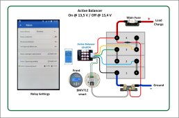
BTW meanwhile i realized I hardly have to use my active balancer, it's off duty most of the time. Part of it is due that my cells are pretty well matched as well my charger stops at cell friendly 13.9V where the voltage difference isn't usually that dramatic. also now with the easy accessable switch the annoying part of plugging in and out the plug which bugged me is gone. I am actually already fine with just the switch together with all the peace of mind providing new knowledge i gained since opening this thread ? (Lvd module, customized active balancer and ESP + relay already ordered?).
But for someone who doesn't monitor his battery frequently, has unmatched cells etc, someone who needs/likes something more automatic, for them our collected solutions will come pretty handy. Before i thought i need a smart solution but now I will test those smart solutions just for the sake of science, to satisfy my curiosity, cause i already ordered it anyway and who knows maybe i will come to prefer them over status quo, discover that the merits outshine the drawbacks (additional parts which could fail, consume energy).☺️
Just some comments : I have designed manufactured and sold more than 100 LiFePO4 BMS Systems, some with passive, some with (very) smart active balancers. I learned that there are so many cases of usage, you can hardly imagine. One of my systems runs on top of a mountain to support a fuel cell powered science station, which is left alone for long periods of time. My own RV is parked for weeks wirh the battery being held at 12.8 Volts only. I rarely check if all is OK...... To cover all these applications I designed my BMS such, that it consumes 0.2 mA total after a Low Voltage Disconnect. There is ample time before there is a risk of a deep discharge.
All of this may explain why I tent to "overdesign" my BMS circuits, not taking into account the individual usage of such a system.....
 
If you wire add-ons to the solar/charge side of the BMS, then they will be disconnected on low voltage. Everyone's usage is different so just need to look at the right solution for your situation.
 
Just some comments : I have designed manufactured and sold more than 100 LiFePO4 BMS Systems, some with passive, some with (very) smart active balancers. I learned that there are so many cases of usage, you can hardly imagine. One of my systems runs on top of a mountain to support a fuel cell powered science station, which is left alone for long periods of time. My own RV is parked for weeks wirh the battery being held at 12.8 Volts only. I rarely check if all is OK...... To cover all these applications I designed my BMS such, that it consumes 0.2 mA total after a Low Voltage Disconnect. There is ample time before there is a risk of a deep discharge.
All of this may explain why I tent to "overdesign" my BMS circuits, not taking into account the individual usage of such a system.....
Very true, if one designs such high end BMS's one has to be prepared for all kinds of possible eventualities since that's also what the customer hopes and pays for.

I also tend to be better safe than sorry and overdesign even my rather mid-range system.
 
I'm not sure what version it was, as I tossed it and replaced it with a new one.

The saga of my failure was in November of 2021, and is posted here: https://diysolarforum.com/threads/active-balancer-or-not.25623/post-383136

The failure caused the caps on one side of the board to get very hot (too hot to touch), and it was creating so much EMI that the Bluetooth of the BMS that was mounted a few inches away was not working well. One cell was rising in voltage rapidly. So yeah, no balancing.

I replaced the balancer with what was probably identical (including version) as I bought two so I had a spare.
Thanks for the info and bringing that thread to my attention! When I read through it i saw many similar ideas, thoughts, solutions and hopes as in this one.

It's clear (led didn't turn on when switched on) that that balancer was already faulty when you installed the switch. Also "relieving" to know that your total breakdown didn't happen when it was switched off but on.
 
I received the xh-m601 but i just realized (sorry about that!?) that it's not a low voltage protection module but an intelligent charger module! Means relay closes (battery charging starts) if battery goes below certain voltage and opens again (charging stops) at a higher set voltage. So basically it doesn't fit for our purpose.
Btw quiescent current was not 0.3mA as stated in a YouTube but 0.2W, 15mA at 13.5V. if relay was closed consumption rose to 40mA.
So go for the yx-x801 https://diysolarforum.com/threads/active-balancer-make-it-smart-?.40192/post-520115 or similar.
If 6mA quiescent current is too high for you maybe wait till Hans finished designing and testing his custom circuit.
 
Last edited:
During my information gathering i found out that if you use an esp32 you still retain the Bluetooth functionality while being able to do things like controlli controlling a relay to make the active balancer smarter. I was told Shadowsteve got it to work to connect with his mobile via his esp32 to the BMS.
Unfortunately i have misinterpreted following reply https://diysolarforum.com/threads/jbd-bms-wi-fi-module.17252/post-520801
I checked with shadowsteve and he told me he still has to reconnect the Bluetooth module if he wants to make changes to the BMS settings.
 
yx-x801 Looks promising but it’d be great to have a 24v or 48v option as well.
 
yx-x801 Looks promising but it’d be great to have a 24v or 48v option as well.
For high voltages like 48 Volts you may use the a.m. design with a 48 V Balancer. The BMV712 can handle high voltages up to 95 Volts.
 

Attachments

  • BMV712 Einbeziehung.jpg
    BMV712 Einbeziehung.jpg
    148.3 KB · Views: 21
Back
Top