diy solar

diy solar

Finally found a LiFePO4 BMS with Low-temp Charging Protection

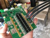
Wow, 30 mosfets, that's a lot for 120 A.

They are 30 V 314 A 1.7 mOhms mosfets. Pretty high spec for a 120 A BMS but they aren't from a top tier manufacturer though. A quick search told me you can get them for 0.75 USD each by 100 quantity but you can bet the manufacturer in china can get them for a fraction of that.

My guess to why they used so many of them is to make the thermal management easier and/or account for pretty loose tolerances between each mosfets.

So yep, you can theorically pass a pretty high current (even double of the BMS rating if you want...) if you keep the fets cold enough but there's other things to account for: the PCB traces are decent but sooner or later they will act like a fuse, there's 2 mOhms current measuring shunt resistors and I have no idea about how much current they can handle (if you want to know you can measure them, deduce the package and use the specs of similar resistors), there's some protections (probably bidirectional TVS diodes, 10 of them in a row at the top) probably against the inductive voltage spike at turn-off and they can't handle an infinite amount of energy either (can't find anything with 1950 IEZ or 1EZ).
mind you there are 15 FETs in each direction. 2 banks back to back.
 
130a each x15, so should I test one at 1,950 amps? or round it up to 2000?

I don't have anything to load it that high....

I do have a 1600w and a 3500 watt inverter, so 425a...
 
mind you there are 15 FETs in each direction. 2 banks back to back.

Yep, I know, but 15 is a lot for 120 A. I use similar Rdson mosfets for 300 A and have only 2x 10 of them (and will probably go down to 2x 9 or 2x 8). The worst case dissipation I have is a total of 44 W at 300 A for the 20 mosfets (and the typical dissipation is 34 W).

130a each x15, so should I test one at 1,950 amps? or round it up to 2000?

I don't have anything to load it that high....

Yeah... don't try that. Current sharing will not be perfect so they will fry before that. Also that's the max current, you need to account for the max dissipation (which is usually a lot lower than max current) because at 130 A per mosfet that would be 862 W for the 30 mosfets...

And the current sense resistors and PCB traces would be long gone at 2 kA anyway ?

I do have a 1600w and a 3500 watt inverter, so 425a...

That's 41 W for the 30 mosfets so with a good heatsink it can be manageable. However the fact they mounted the mosfets the way they did make the heatsink contact area only on the plastic package instead of the thermal pad so the Rth will be pretty high. They may not be able to handle that even if you use some water-cooling.
 
That's 41 W for the 30 mosfets so with a good heatsink it can be manageable. However the fact they mounted the mosfets the way they did make the heatsink contact area only on the plastic package instead of the thermal pad so the Rth will be pretty high. They may not be able to handle that even if you use some water-cooling.

good point. my first thought is solder a copper bar on edge in between the row of FETs so its soldered directly to the metal part
 
They are too close to each other to do that (without a high risk of heat damage while soldering anyway), plus it would contact only the end of the mosfet tab and that's like less than 5 % of the surface of the thermal pad and far away from the die so the Rth would still be pretty high.
 
They are too close to each other to do that (without a high risk of heat damage while soldering anyway), plus it would contact only the end of the mosfet tab and that's like less than 5 % of the surface of the thermal pad and far away from the die so the Rth would still be pretty high.
My main book learning about all this stuff ended almost 50 years ago and still involved vacuum tubes for a lot of it. Transistors were still the new thing, too. It didn't take you long to lose me. I can't remember if we even used thermal paste of any type. LOL, still interesting to read both of your thoughts...... :unsure:
 
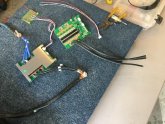
This pic is from eBay and because it only has 2 wires per side, I think it isn't the 120A version.....
There are 5 spots for sockets that aren't populated and spots on the board that aren't either. It would be interesting to know what they left off these PCBs and they do.

s-l1600.jpg
 
Last edited:
There's a telltale in the heat-goop: only 4 pairs of FETs on the other side, so 12 instead of 15
 
I have them in my hand right now, I can ship today. I just disabled the Amazon-fulfilled inventory so if you order it now I will ship it.

remember the BT module is sold separately.

I already ordered from the amazon prime link but it says it says it will come April 22? If I buy from amazon now (through you) the BMS + bluetooth now is $139.41 including tax. Double what aliexpress is. Can I order directly through you with a discount? Battery hookup were $81 (including bluetooth module and forum discount) before they ran out of stock.
 
I already ordered from the amazon prime link but it says it says it will come April 22? If I buy from amazon now (through you) the BMS + bluetooth now is $139.41 including tax. Double what aliexpress is. Can I order directly through you with a discount? Battery hookup were $81 (including bluetooth module and forum discount) before they ran out of stock.
If you cancel the amazon order and redo it I will ship in the morning.

I can do a BMS w/BT module for $115 if you send the money to me on zelle. $119 on paypal. shipping included.

I recently raised the price by $10 because I got charged a 25% import tariff by US customs on the last shipment.

Did BH charge shipping on top of that?
I think they may have charged around $5 for USPS shipping.
 
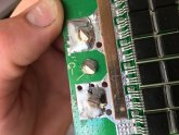
All, I figured out a good method for soldering and de-soldering 8ga wires on a BMS.

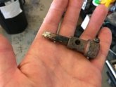
first I tried this torch tip:
B8C7D372-B261-4707-8FFB-F9249B6F34BE.jpeg
It didn’t work, don’t waste your time.

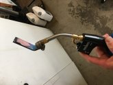
next, I tried heating up a scrap of copper and using that to heat the solder. This works but you need extra hands. So I refined the tool by bending a scrap of copper bus bar and clamping it to the torch tip:
9E264526-E7CF-490C-B986-BCEAC071755C.jpeg
This is excellent. You just get it super hot then shut off the torch and use it as a soldering iron. This chunk of copper holds enough heat to make it work.
4C2769E7-8125-43B5-8401-DB92884ED322.jpeg
EB4AA968-470C-43D0-BA35-5E9BE00299D8.jpeg
A5F5CA44-7C67-4B26-8E51-BEBED1265FED.jpeg
Video coming soon.
 
Very Cool..... Excellaente......
Thje extra length of wires, lets you customize it for your setup, in mounting the BMS and running out to a external Negative terminal/ground bus. Without haven't to splice the wires.

@mndare check this out if you have to build another BMS for your builds.
 
Archie,
I've read that the Chargery BMS's need other items to work, things like Temp Sensor, relay wire, shunts, etc.. If this is true, can you tell me what else I'd need to buy? I've got 16 3.2v 152Ah cells for my 48v system arriving tomorrow and the BMS I ordered is not expected to ship from China until 29 April.
Thanks for your help!
I am looking at these and see options to buy "with accessories"! Likely the best way to go, and maybe a relay is extra you need if going that route. My take as newbie still learning in pre-purchase mode for 1st DIY LifePO4 build/ and Alibaba purchase.
 
Hi Will,
You really ought to look at the Chargery BMS16T. I just got one. They are not cheap but will handle up to 500A and can use external relays. They claim to support low temp cutoff although mine is still in the box. The "T" on the end of the model name is very important. The regular BMS16 does not balance cells.
Wow: Just examining this what look like new version of Chargery ... Look Good . for Active cell balance plus options for bttery voltage selection ???
 
Very Cool..... Excellaente......
Thje extra length of wires, lets you customize it for your setup, in mounting the BMS and running out to a external Negative terminal/ground bus. Without haven't to splice the wires.

@mndare check this out if you have to build another BMS for your builds.
Smart thinking, Great idea. I have two more BMS coming so I will try this method. Kick ass dudes
 
Smart thinking, Great idea. I have two more BMS coming so I will try this method. Kick ass dudes
When you do it, if you have an infrared thermometer it would be interesting to know how hot you need to melt the solder.

Your work showed that they could be upgraded to 8AWG wires, and overkilSolar Steve took it to the next level, after I pointed him in the right direction. Just another thing that shows the value of these forums and the people who post here.
 
Last edited:
Nice but I’m curious if the 10-32 bolt and nut is still a viable option? It seems a much cleaner and more versatile system.

still researching the terms and settings for the parameters.

Will, is it possible you could take a screen shot of yours and post it? Looking for some conservative settings in the range of 80/20, thanks in advance...
 
Back
Top