diy solar

diy solar

Dc mini breaker confusion

Mannfamilywoodworks

Solar Enthusiast
Joined
May 8, 2022
Messages
292
Location
Ny
Hello
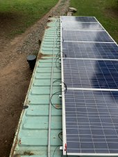
I’m about to power on my system and start charging my new eg4 battery.
I wanted to triple check everything prior.
One thing is holding me up from turning everything on and I’m confused…
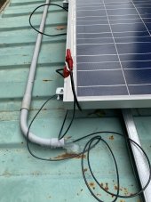
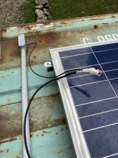
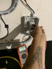
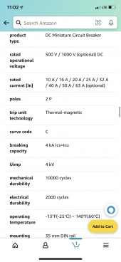
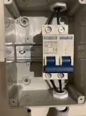
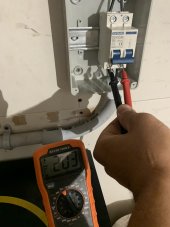
I’ve got this dc circuit breaker installed between my inverter and panels. My inputs are reading 200v with my multimeter with the breaker in the off position.
As soon as I switch the breaker to the on position it automatically switches to 1v?
Anyone know why?
I’m going to include pictures of the breaker and the specs.
 

Attachments

  • 43B77C18-3DEF-47E8-B588-EF6789F799F9.png
    43B77C18-3DEF-47E8-B588-EF6789F799F9.png
    574.8 KB · Views: 7
This is a 63 amp breaker.
I’m realizing now that this is way bigger than I need.
I have 6 -235 watt panels hooked up in series.
They’re around 33v-37vx6
and 8amps if I remember correctly.
 

Attachments

  • image.jpg
    image.jpg
    95.8 KB · Views: 28
You don't need over current protection for a single string.
It is pretty handy to have a means of disconnect which the breaker provides.
I don't know why you get 1 volt when you enable the breaker.
Is your string wired correctly?
What is the max voltage for the solar charge controller in your all-in-one?

I wanted it for ease of working on the system and safety.
Max voltage is 250v for solar charge controller.
I’m pretty sure my string is wired correctly.
I’m going to check for the fourth time to make sure I didn’t switch the - and + wires or something like that
 
37 * 6 = 222 volts.
That is pretty darn close to the limit.
If it gets cold where you are you might smoke your controller.
 
This is a 63 amp breaker.
I’m realizing now that this is way bigger than I need.
I have 6 -235 watt panels hooked up in series.
They’re around 33v-37vx6
and 8amps if I remember correctly.

Have you ever shut that breaker off under full load?

I just wonder if it'll actually extinguish the arc. Lot of fake DC breakers around
 
37 * 6 = 222 volts.
That is pretty darn close to the limit.
If it gets cold where you are you might smoke your controller.
I’ll be switching to 3s-2p in a week or so to bring that down.
Honestly I might go do it now.
I’ve got all my mc4 connectors and the tool to do it.
 
Oh yeah I do!
It means you have reverse polarity.
Send a thank-you note to the inverter manufacturer for including a clamping diode.
I haven’t turned the inverter on yet thankfully.
What exactly should I do right now?
How do I make my polarity correct?
 
%100 what the issue was.
%100 user error.
I have no idea how I did that.
I color coded all the wiring.
I got shocked by the 200v when I switched the input onto the breaker and I’m still not fully awake.
I believe I must’ve mixed it up when I went from exterior to interior or the container.
I love electrical work but I’ve only been dabbling in this trade for less than 4 months.
I appreciate everyone’s input and I’m definitely going to be more careful in the future and always quadruple check my polarity.
 

Attachments

  • image.jpg
    image.jpg
    112.8 KB · Views: 28
Ignore everything on the roof. Just put volt meter across terminals of inverter. See if polarity of that 1V matches polarity indicated on inverter.
You're not the first to do this.
 
Ignore everything on the roof. Just put volt meter across terminals of inverter. See if polarity of that 1V matches polarity indicated on inverter.
You're not the first to do this.
I simply switched the wires leading into the breaker and it worked fine.
 
The thing you should have done was check polarity on PV side prior to closing switch.
If inverter side is concealed, then after confirming zero volts on that side see if you can verify connections (desired polarity at breaker) with ohm meter.

You can connect PV panels and wires in series safely so long as both ends of next component are visible, open-circuit.
Once you complete a loop (through conduit, or two strings in parallel), it is possible to get current flow. So I check voltage between MC4 pair before mating. It may read a few hundred volts then rapidly decay as parasitic capacitance is charging.

When you stick a DMM probe in an MC4 connector, it is no longer touch-safe; both probes are hot and can shock you, so be careful.
A nice set of test leads with retainers clipped off MC4 and shrouded banana plugs would be the ideal setup.
 
Care to explain what this clamping diode is exactly?

"Reverse polarity protection"

If you hook 200V reverse polarity to inverter, it drives electrolytic capacitors backwards and they blow up. Maybe other things too.
A blocking diode could have held off the voltage, but would have voltage drop in normal operation, causing power loss.
A backwards diode across +/- shorts them out to about 1V or so under reverse polarity. That prevents damage.
This is one reason why there is a maximum Isc spec on MPPT inputs.

In the past, some brands of inverters didn't have the diode, and suffered near 50% failure during install.

This works well for PV, limited current. Not good for battery or AC powered DC supplies. Those may used back-to-back FETs. More expensive and limited voltage range. Typically also used to implement inrush limiting.
 
The thing you should have done was check polarity on PV side prior to closing switch.
If inverter side is concealed, then after confirming zero volts on that side see if you can verify connections (desired polarity at breaker) with ohm meter.

You can connect PV panels and wires in series safely so long as both ends of next component are visible, open-circuit.
Once you complete a loop (through conduit, or two strings in parallel), it is possible to get current flow. So I check voltage between MC4 pair before mating. It may read a few hundred volts then rapidly decay as parasitic capacitance is charging.

When you stick a DMM probe in an MC4 connector, it is no longer touch-safe; both probes are hot and can shock you, so be careful.
A nice set of test leads with retainers clipped off MC4 and shrouded banana plugs would be the ideal setup.
There’s several things in your response that I need to do more research on.
I appreciate your response and it makes perfect sense and I’m grateful for the blocking diode.
I’m also grateful for you for explaining this to me and quickly helping me out.
 
Have you ever shut that breaker off under full load?

I just wonder if it'll actually extinguish the arc. Lot of fake DC breakers around
Funny you say this.
I didn’t think to test the breaker in the “on”position and the “off” position at first.
After you said this I decided to test it.

it still allows 50ish volts to go through it?
Why is this?
It’s a breaker I got off Amazon.
 

diy solar

diy solar
Back
Top