fromport
Solar Addict
it does and that why it goes to zero when he connects things.Does that say negative 203 volts?
*ouch* I hope the input of your inverter survived


it does and that why it goes to zero when he connects things.Does that say negative 203 volts?
All is well ?it does and that why it goes to zero when he connects things.
*ouch* I hope the input of your inverter survived
Funny you say this.
I didn’t think to test the breaker in the “on”position and the “off” position at first.
After you said this I decided to test it.
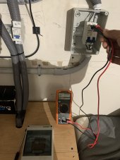
it still allows 50ish volts to go through it?
Why is this?
It’s a breaker I got off Amazon.
Positive side
Edithoto didn’t load
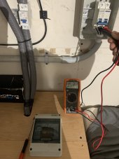
Negative side
I purchased a mc4 kit and a bunch of connectors I was planning on using those!Regarding your wire splicing methods ...
Unless those are grease-filled wire nuts, they may deteriorate with moisture.
Uh, does your inverter have AFCI? I think you may be needing that.
What I do is run conduit to a junction box. Cut a 1m MC cable in half, use as pigtails coming out of the box.
They can go through a compression gland, or bottom of the box to be drip-proof.
Ahhh I didn’t think about that. Okay that makes more senseThat 50V may be backfed from your inverter. People have reported getting shocked from PV input terminals with no PV connected.
You could test with breaker isolated from inverter.
Or, with battery and any AC sources isolated from inverter.
it still allows 50ish volts to go through it?
Why is this?
That 50V may be backfed from your inverter. People have reported getting shocked from PV input terminals with no PV connected.
Can't recall the thread but @RCinFLA explained some of that recently. Maybe he'll link to it or charitably do it again.That 50V may be backfed from your inverter. People have reported getting shocked from PV input terminals with no PV connected.
I purchased a mc4 kit and a bunch of connectors I was planning on using those!
I just did this for testing purposes temporarily
Wow that’s really good to know and to be aware of.I've avoided having to do crimp terminations as much as possible. Still don't have proper tool for MC4, tried to use a Harbor Freight hydraulic hex crimper.
Mostly, I buy ready-made MC wire (MC3 or MC4) and cut in half.
I bought a lot of surplus junction boxes, which has kept me supplied in pigtails for all the test setups I put together (wires into switchboxes, to connect ammeter or short/connect load. Reconfigurable wiring on the garage floor before installing inverter.)
I did install some MC3 on ends of PV panel wires that had been cut. It would help to have correct size contact for the wire gauge, and correct size boot for the insulation. I used wire lube but it was still tough. Someone told me soften them in hot water, will try that next time.
I think originally MC4 was MC4 was MC4. Following the Walmart disasters, now the mated pair is only UL listed if the specific brands being used together have been tested and received UL listing together. Brand A may be listed with brand B, Brand B may be with brand C, but Brand A is not UL listed with brand C and is a fire hazard. Data sheet for your panels will declare which brands it can be mated with. i.e., you have the opportunity to not use that MC kit (unless it is the right brand/model), if you want to go by the book and be as safe as possible.
My system has been off for three days while I was away working. These capacitors should be fully drained of power after 72 hours? Is that correct?Your charge controller has large capacitors on the PV input. They can stay charged even after you disconnect PV. This is probably what you're reading.
Of course caps can hold voltage. I watch mine discharge, relatively fast. I think that is designed in as a safety feature.
Off-brands maybe not.
I’m guessing I don’t get that or I do lol?Yeah a good designed should have a 5k or 10k resistor across the cap terminals to drain them when powered off.
But that is probably too much of an expense in many controllers
That’s actually a great test and idea. I’m going to test that next time I power down the system. Thankyou very much.If your voltage 'drained' somehow or another, you don't have anything to worry about other than to remember that just because you've flipped the breaker off doesn't mean there is instantly 0 volts on the other side. You either need to measure and wait until it drops to a safe level before touching it, or just come back later. It would help to measure the voltage 'rate of change' at least once just so you can ballpark how long you have to leave it alone before it drops to a low enough voltage to stop worrying about it.
And check both AC and DC volts to be safe. Arguably 50v DC is already unlikely to hurt you, but i still avoid touching it and there is a thread going on elsewhere where someone recently recounted some slight nerve damage in a finger gotten from a ~48v system. But there could be AC volts on there too, so just check both, establish a rough timeline of how long you need to let it 'drain' until you're comfortable touching it, and then use that info for all future occasions that you have to work on it. And preferably still verify with a meter anyway, because everything works the way it usually does, until it doesn't. ?
You need a much better weatherproof connection than wire nuts in tape. Actually not much better. You need a good weatherproof connection.Positive side
Edit
Depends on the brand.Hopefully I can use these mc4 kits as I hoped lol it was a whole 30ish dollars spent.
That really surprised me!Still don't have proper tool for MC4,
As I did. The key is to keep all connectors the same brand and check them at least yearly.One cheapie brand that worked for me (over a year later and no failures) was Bouge RV. I bought a gazillion pairs and changed every one. Because I also proved mixing ‘brands’ also leak and the cheap brands have even been ferrous (magnet proves it).
(Still don't have proper tool for MC4)Use a proper ‘B’ crimper and you’ll be fine.
That really surprised me!
It might have taken a year but after seeing PV production drop I opened up the connectors and all the "mismatched" MC4s (original panel connectors to Bouge RV) had corroded to some extent, some pretty badly.