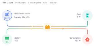
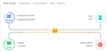
I just used the regular Ethernet cables provided. Plugged into the CAN port.Can you please tell me the pin layout you used of the cable between the MR & the Jakiper?
You are using an out of date browser. It may not display this or other websites correctly.
You should upgrade or use an alternative browser.
You should upgrade or use an alternative browser.
Megarevo RxLNA Discussion
- Thread starter jsmetalcraft
- Start date
So I just found a snag. It seemed like everything was working fine until the batteries were fully charged. Then the inverter limited the PV input instead of putting the power back to the grid. Can anyone tell me if there’s a setting I am missing to achieve this?
Further example, if I have the battery disconnected the PV will dump full current into my loads which currently I am just running my garage so little to no usage, the rest of the power is returned to the grid. When the batteries are connected, all bms info is displayed on the inverter correctly. Once again it will power the loads and charge the batteries. Once full, the inverter will go down to almost 0 current and then limit the PV input. I have tried this on batt priority, self consume, eps on and off. I am still running the original firmware.So I just found a snag. It seemed like everything was working fine until the batteries were fully charged. Then the inverter limited the PV input instead of putting the power back to the grid. Can anyone tell me if there’s a setting I am missing to achieve this?
fromport
Solar Addict
I would love to go through the menu's and get a good explanation of each setting. I have downloaded most manuals of all MR clones and they basically have all the same text, but not a good explanation.Further example, if I have the battery disconnected the PV will dump full current into my loads which currently I am just running my garage so little to no usage, the rest of the power is returned to the grid. When the batteries are connected, all bms info is displayed on the inverter correctly. Once again it will power the loads and charge the batteries. Once full, the inverter will go down to almost 0 current and then limit the PV input. I have tried this on batt priority, self consume, eps on and off. I am still running the original firmware.
I ran my unit for months without batteries and when put to self-consume it would backfeed to the grid.
Then I started putting loads on a critical load panel behind the MR. So far so good. I have my Li-Ion batteries hooked up but even when I put it to lead acid battery settings, i set the max charge voltage to 57.6, max charge amp to 10 amp, overvoltage protection to 58,
My batteries have 4 LED indicators that seem to indicate 25% SOC each, one is only lit up when I switch it on, and voltage , with no load is 49.9 volt. So the battery seems to charge a while and then my batteries disconnect and trigger an alarm on the MR:
Bat over vol
14: Bus over vol
I can imagine when you are charging the batteries and the battery disconnects the battery voltage goes up and might trigger the OVP.
But why/what is the "Bus over vol" has to do with that ?
My MR shut down, lost power to all at the critical load.
Decided to go without a battery for a while again.
When I shut everything down and left the load on, as soon as I enabled the grid again, the CLP was powered again, then I enabled PV and like you describe, the PV was only used to make up the load (again in my case no batteries) , not put the extra energy back into the grid.
I then shut everything down, including load breakers.
Then turned on the PV, waited till it started feeding back into the grid and then enabled the load.
Now it is still in that state. PV providing the load & putting the back into the grid.
Would be really something if the way things are started determines the behavior of the MR instead of the meny settings.
Maybe something you are willing to try ?
My setting is for "self consume" btw.
Do you have the CT's connected and where are they connected in your setup ?
No CTs. I have net metering so I’d like to dump all the extra power back to the grid. I wanted to have the MR use the batteries first overnight and when depleted in the morning, charge first and then dump the rest back the grid. I have disconnected the batteries and set it back to lead acid so I dump full power to the grid until I can figure this out. I don’t want to waste energy if possible. What would be the recommended disc depth setting?
fromport
Solar Addict
technically 80% DOD (depth of discharge) should be allowed, but I would limit it to 75% .What would be the recommended disc depth setting?
But I am confused about the menu structure:
Do you put in 80 or 20 in the field?
Currently my powerman shows this:

I know I am backfeeding to the grid, why isn't that showing ?
argghh... this unit is really something....
fromport
Solar Addict
argghh... this unit is really something....
Looking at this picture from the MR manual I decided to cut off the RJ45 plugs from the cable between the master battery & the MR

Even though the people I contacted for support said the communication between MR & batteries was RS485, i hooked up 5 pins:
4 blue
5 blue stripe
6 green
7 brown stripe
8 brown
On both sides of the cat5 cable.
I expected nothing and with RS485 setting I got a "failure to communicate"
Then I switched to CANBUS and ....

\o/
Now I am motivated (at one of the hottest days of the year 106F/41.1C ) to hook up my other 2 batteries as well!
I am going out there!!
fromport
Solar Addict
My batteries were relatively easy to fill it seems. And once they were full the MR continued to feed back into the gridFurther example, if I have the battery disconnected the PV will dump full current into my loads which currently I am just running my garage so little to no usage, the rest of the power is returned to the grid. When the batteries are connected, all bms info is displayed on the inverter correctly. Once again it will power the loads and charge the batteries. Once full, the inverter will go down to almost 0 current and then limit the PV input. I have tried this on batt priority, self consume, eps on and off. I am still running the original firmware.
We might have to compare settings of the battery.
What version of the firmware are you running (what version is your original?)
fromport
Solar Addict
Some of the screens in ASCII that I photographed from the screen of the MR once the battery was recognized and working:
BATTERY INFO
TYPE: Lithum
TEMP: 31°C
BMS PRMETER
CHAR VOL: 54.0 V
CHARGE: 50A
DISCHA: 100A
STATE
SYS: PV GRID
INV: GRID
DCDC: CHARGE (screenshot was taken while unit was charging batteries)
SYSTEM2
BMS Com: CAN
Anti Reve: DISA
DOD: 80%
BATTERY
VOLT: 51.6 V
CURR: 21.8A
STA: C D
Later when charging had finished the last screen had changed to:
BATTERY
VOLT: 50.4V
CURR: -1.4A
STA: D
Anyone has any idea what those indicators mean ?
STA = Status?
C = Charge ?
D = Discharge ?
Firmware arm: v1.03.06 DSP: v1.04.06
Your settings are pretty identical to mine but there isn’t a discharge current setting with this firmware.
I think you are correct with the D and C induction.
I should just update the firmware but I’m a little reluctant, with how things go with this inverter that I’ll brick it.
Your settings are pretty identical to mine but there isn’t a discharge current setting with this firmware.
I think you are correct with the D and C induction.
I should just update the firmware but I’m a little reluctant, with how things go with this inverter that I’ll brick it.
fromport
Solar Addict
I honestly tried. I had a celeron linux laptop with only 4GB ram , i installed a virtual win10 machine. could only give it 3GB ram, 1 core . slow as in typing speed was terrible. But the program worked. Once it gave an error while flashing, retried and it went through without a hitch.Firmware arm: v1.03.06 DSP: v1.04.06
Your settings are pretty identical to mine but there isn’t a discharge current setting with this firmware.
I think you are correct with the D and C induction.
I should just update the firmware but I’m a little reluctant, with how things go with this inverter that I’ll brick it.
Then I bought a used laptop on Craigslist with 16GB ram, so now my virtual win10 has 6GB to play with and it "flies".
Don't be too afraid. the system seems pretty robust (in that area) ;-)
fromport
Solar Addict
AbsolutelyMaybe I’ll try that tomorrow.
So when your battery bank is full, you are pushing full PV current back to the grid?
Look at this graph:

My batteries had been disconnected since December last year when they shipped them from .cn
So it needed some charge and once it got to 97% SOC battery charging stopped and kept feeding back into the grid (blue line is total power from PV)
fromport
Solar Addict
These are my ASCII settings from the pictures I took from my settings menu:So when your battery bank is full, you are pushing full PV current back to the grid?
Menu settings depend on firmware so that is what I start with:
ARM: V1.03.12
DSP: V2.04.12
SETUP
1. -- SYS SETTING --
1: WORK MODE -> 1. SELF CONSUME
2: EPS ENABLE -> 2. ENABLE
3: BAT WAKE-UP -> 2. ENABLE
4: REMOTE CTRL -> 2. ENABLE
5: START DELAY -> START-UP DELAY INPUT: 20 UNIT: SEC
6: PV INPUT -> 1. INDEPENDANT (I have 3 mppt's in use with 3 different arrays)
7: Anti Reverse -> 1. DISABLE
8: ARC ENABLE -> 1. DISABLE
9: BUTT ENABLE -> 1. DISABLE
2. --BAT SETTING--
1: BAT TYPE -> 3:Lithum
2: DISC-DEPTH -> GRID DOD: 080% OFFGridDOD: 080% Return: 040% (not sure what the return means)
3: CHARG-CURR -> INPUT: 045 UNIT: A
4: BAT-COMM -> 2: CAN
3. --GRID STD-- -> 9:US-CA ( I assume short for USA-CANADA?)
4. --GRID SET-- -> 2: 120V/240V
5. RUN SETTING -> 1: REACT MODE -> 1. POWER FACTOR -> 1.0
2: GRID POWER -> -GRID PERCENT_ INPUT: 090%
3: DISC POWER -> -DISC PERCENT- INPUT: 100%
4: PV POWER -> -PV PERCENT- INPUT: 100%
5: VAC-MIN -> -GRID VOLT LOW- INPUT: 150 UNIT: V
6: VAC-MAX -> -GRID VOLT HIGH- INPUT: 280 UNIT: V
7: FAC-MIN -> -GRID FREQ LOW- INPUT: 57.0 UNIT: Hz
8: FAC-MAX -> -GRID FREQ HIGH- INPUT: 63.0 UNIT: Hz
9: ACTIVE REP. -> -ACTIVE TYPE-
1. PWR-VOLT RES -> -PWR-VOLTAGE- -> 2. ENABLE
2. PWR-FREQ RES -> -PWR-FREQUENCY -> 2. ENABLE
3. PFC-VOLT RES -> -PFC-VOLTAGE- -> 2. ENABLE
4. PFC-FREQ RES -> -PFC-FREQUENCY -> 1. DISABLE
5. ACTIVEISLAND -> -ACTIVEISLAND- -> two options: 1.DISABLE 2.ENABLE no option highlighted, i will leave it that way ;-)
6. Leack Curren -> -Leack Dete- -> 1. DISABLE
7. Insulation d -> -Insul Dete- -> 1. DISABLE
6: 485 ADDRESS
7: BAUD RATE
8: LANGUAGE
9: BACKLIGHT
10: DATE/TIME
11: CLEAR REC
12: PASSWORD
13: MAINTENANCE
14: FCTRY RESET
15: PARALLEL
These are all the settings that I think are important for now.
Could you check and highlight the differences in your setup?
Last edited:
fromport
Solar Addict
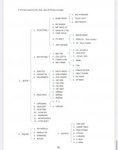
I don't think it will hurt to upgrade your firmware.I do not have many of those menu’s you have. This is the ones I have with this firmware.View attachment 110207
Apart from new options, I am pretty sure there are also bug fixes included
fromport
Solar Addict
But you can roughly compare then and hightlight the differences between your & my settings?I do not have many of those menu’s you have. This is the ones I have with this firmware.
I just updated the firmware and all my settings are the same as yours. My battery is at 99% SOC and it is finally outputting to the grid. It is weird though. It is showing INV: L1 putting out 13.5A and L2 putting out 11.4A. They used to be matching...? Those numbers seem awful low. My Tigo app is showing 5.1KWH to the inverter. Just before the upgrade (a few mins prior, same clear sky) I was getting 25A per phase on the INV output screen.
Similar threads
- Replies
- 213
- Views
- 15K
- Replies
- 30
- Views
- 3K
- Replies
- 5
- Views
- 484


