diy solar

diy solar

JK BMS CAN bus comms now possible for inverters that support Goodwe and Pylontech batteries

I think float is not needed for lifepo4 battery.

Yes I think so too, but I wonder why most of the commercial chargers still have it enabled, like victron etc.

Is the chargeV and bulk voltage configurable?
chargeV, bulk and absorption voltage are all same voltage and is configurable, just a little different is how they are used to charge.
chargeV/bulk voltage is constant current(CC), voltage will rise and current stays constant(it maybe be less than constant when using solar to charge)
absorption is constant voltage charging(CV) Voltage is held constant, current will reduce to near zero.
 
Float is practically the same as absorption to a point. Absorption should stop once current drops below 0.05C, whereas float will maintain a set voltage for as long as sufficient input energy exists.

Absorption is best for LiFePO4, whereas float is preferable for lead acid.
 
Absorption is best for LiFePO4, whereas float is preferable for lead acid.

Yes but strange that Victron and many other vendors have a specific LiFePO4 charging profile but have chosen to have both Absorption and float.

Default profile for Victron LiFePO4:
Absorption voltage: 56.80V
Absorption time: 2h
Float voltage: 54.00V
Re-bulk voltage offset: 0.4V drop below float (53.6v default setting)
 
Last edited:
Hi,

That looks to be a newer model, so I can't say for sure but if it is the same as all the other models RS485 should be active.
I would double check with the seller.
If it helps, I am using a newly ordered B2A24S15P-CAN which has both CAN and RS485. I am using RS485 for this, works fine.
 
@uksa007 some clarification:
1) Is the Vcc of TJA1050 connected to 5V pin of Esp32?
2) how are you powering th esp32? I thorough usb or 5v pin
3) did you connect any power to 3.3v pin of esp32
4) if esp32 is powered through USB, can TJA1050 get power from 5v pin of Esp32?
 
@uksa007 some clarification:
1) Is the Vcc of TJA1050 connected to 5V pin of Esp32?
2) how are you powering th esp32? I thorough usb or 5v pin
3) did you connect any power to 3.3v pin of esp32
4) if esp32 is powered through USB, can TJA1050 get power from 5v pin of Esp32?

Hi,
1) Yes
2) From USB but you could also power from 5V pin.
3) NO you need 5V for the TJA1050
4) Yes

Please see this link for more info on connecting the TJA1050
 
Hi,
1) Yes
2) From USB but you could also power from 5V pin.
3) NO you need 5V for the TJA1050
4) Yes

Please see this link for more info on connecting the TJA1050
Thanks for your feedback. The esp32-example-can.yaml file specifies that GPIO 16 and 17 is connected between bms and esp32 but readme.md has this line:
*Connect a TJA1050 to an ESP32 (default GPIO 17 TX, 16 RX) as per https://esphome.io/components/canbus.html?highlight=can#wiring-options*.
Which is the correct one?
These are the pins I use:

Code:
# GPIO pins your JK-BMS RS485(TTL) is connected to the ESP TX->RX and RX->TX.
  tx_pin: GPIO17
  rx_pin: GPIO16
# GPIO pins your CAN bus transceiver(TJA1050) is connected to the ESP, note! TX->TX and RX->RX.
  can_tx_pin: GPIO23
  can_rx_pin: GPIO22
 
Last edited:
Great work indeed !
It's exactly what I'm looking for my project to enable the communication of my Deye inverter with DIY battery pack (16 cells ) and BMS
I try to understand what commercial BMS like Daly,JBD,JK BMS are compatible with Deye phiscal interface and application protocol but I understand that none of them is compatible off the shelf (I got suggestion to use SEPLOS) !
Then I discover this nice bridge/protocol adapter and seems really a simple and low cost solution..will offer you a beer for sure !
Just a question, are you going to make the same protocol conversion also for JBD and Daly BMS ?
For some reason I prefer JBD, but since I have still not bought the BMS for my project so I can switch to JK if is the only compatible with Deye

thanks again for this application

Davide
 
Just a question, are you going to make the same protocol conversion also for JBD and Daly BMS ?
Sorry we only support these JK-BMS:

 
Hi uksa007, really cool project.

Have you considered support for multiple JK BMS? I guess you would be looking at summing some values, averaging others, and passing through all alarms to make it look like one big pack.
 
Have you considered support for multiple JK BMS? I guess you would be looking at summing some values, averaging others, and passing through all alarms to make it look like one big pack.
I have briefly thought about it, there are few hurdles that may prevent it from being simple, like the code that reads the JK-BMS values may not easily support multiple BMS, both hardware serial ports are already used on ESP32 etc.

At the moment I'm focused on improving the charging logic and overall user experience, ensure everything works as it should.

My thoughts at the moment are if you need more capacity just add more of the same cells in parallel then you don't need another BMS.
EG 2P16S, 3P16S etc.
 
Last edited:
I have briefly thought about it, there are few hurdles that may prevent it from being simple, like the code that reads the JK-BMS values may not easily support multiple BMS, both hardware serial ports are already used on ESP32 etc.

At the moment I'm focused on improving the charging logic and overall user experience, ensure everything works as it should.

My thoughts at the moment are if you need more capacity just add more of the same cells in parallel then you don't need another BMS.
EG 2P16S, 3P16S etc.
You just need to add a analog switch like TMUX1309, and use 2 io pins and one serial port to control 4 bms. ;-)
 
Last edited:
What are the steps to upgrade from one version to another when it's in operation.
 
What are the steps to upgrade from one version to another when it's in operation.
Just the same as when you first flash it:
Check the yaml file and set the configuration at the top, eg charging voltage, number of packs etc.
Compile and flash using "esphome run esp32-can-example.yaml"
Communication with the inverter will be lost for a few seconds while it flashes and reboots.
The inverter may stop charging/discharging the battery until it receives comms, unusually only a few seconds.
Done.
 
Last edited:
I am waiting for my devkit and TJA1050 to arrive to use this your wonderful app. Thanks once again for making this open source.

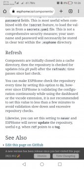
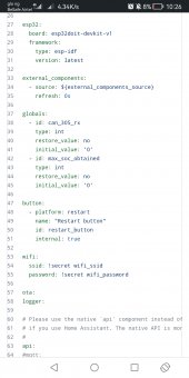
Please just one observation: the external component is set to refresh every now and then as against recommended minimum of a minute. What does this entail? Won't it be drain on the resources if it keeps checking like this? What is the implication if one sets it to NEVER?

It appears you are working on Bluetooth support as well.

Thanks
 

Attachments

  • Screenshot_20221112_102639_com.android.chrome.jpg
    Screenshot_20221112_102639_com.android.chrome.jpg
    279.4 KB · Views: 27
  • Screenshot_20221112_102612_com.android.chrome.jpg
    Screenshot_20221112_102612_com.android.chrome.jpg
    155.3 KB · Views: 29
Please just one observation: the external component is set to refresh every now and then as against recommended minimum of a minute. What does this entail? Won't it be drain on the resources if it keeps checking like this? What is the implication if one sets it to NEVER?

It appears you are working on Bluetooth support as well.

The external components are downloaded when flashing. I haven’t seen any issues with it checking every time.

No, not working on Bluetooth support, the original code I use to read the BMS does, but I don’t recommend it or support it, as the inverter needs a CAN packet every second, Bluetooth is not reliable enough.
 
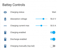
Sneak peak of what i have been working on:
Complete rework of the charging logic, now charges with constant current(CC) to the absorption voltage, then has an absorption timer (Constant Voltage, user configurable time), with rebulk feature (user configurable offset from absorption voltage).
Live sliders for absorption voltage and charging current (can change on the fly!)
Charging status user feedback to let you know what the charging logic is doing. Bulk, Absorption, Complete, Wait , Disabled, etc
Reworked the Charge/Discharge controls and logic, so more user friendly (default to on as below).

1668323326808.png
 
Last edited:
Sneak peak of what i have been working on:
Complete rework of the charging logic, now charges with constant current(CC) to the absorption voltage, then has an absorption timer (Constant Voltage, user configurable time), with rebulk feature (user configurable offset from absorption voltage).
Live sliders for absorption voltage and charging current (can change on the fly!)
Charging status user feedback to let you know what the charging logic is doing. Bulk, Absorption, Complete, Wait , Disabled, etc
Reworked the Charge/Discharge controls and logic, so more user friendly (default to on as below).

View attachment 120009
If 90% SoC is reached and the absorption time has not been exhausted, will it exit absorbtion or it will continue till the end of the set time?
 
If 90% SoC is reached and the absorption time has not been exhausted, will it exit absorbtion or it will continue till the end of the set time?
It would be when it hits the rebulk voltage(not 90%), it will stop absorption and start bulk followed by absorption.
 
this is great, thanks for the work uksa007!
I have been thinking about the possibility to expand so 2 JK bms packs in parallel could work together, processing values sent to the inverter something like so ;

  • Battery Voltage = average
  • Battery Current (+charge, -discharge) = sum
  • State of Charge (SOC) = average
  • State of health (SOH) = average/not super important
  • BMS Temperature = average or highest
  • Charging Voltage = average
  • Charging Amps = sum
  • Discharge min Voltage
  • Battery name
  • Alarms: Cell over/under voltage, Charge/discharge over current, High/low Temp, BMS fault = pass through from either bms
  • Charging logic: Chargers to user defined max SOC(90%), turns off charge, will restart charging if SOC drops below user defined rebulk SOC(80%).
I had a look and the ESP32 actually has 3 UARTs, but UART0 is used for firmware flashing etc and it seems from a quick google that people generally have difficulty using it, would it be possible to add an rs485 to i2c converter to enable comms to the second BMS?
thoughts?
cheers :)
 
I have been thinking about the possibility to expand so 2 JK bms packs in parallel could work together
I have briefly thought about it, there are few hurdles that may prevent it from being simple, like the code that reads the JK-BMS values may not easily support multiple BMS, both hardware serial ports are already used on ESP32 etc.

At the moment I'm focused on improving the charging logic and overall user experience, ensure everything works as it should.

My thoughts at the moment are if you need more capacity just add more of the same cells in parallel then you don't need another BMS.
EG 2P16S, 3P16S etc.

untitled-png.69433
 
Last edited:
Multiplex
There are lots of options to resolve, probably the easiest would be to use software serial, the real problem is current codes does not support reading multiple BMS, it would take lots of development, including buying another BMS and set of batteries, so I can test and develop costing a few thousand dollars. Not something that I plan on doing any time soon.

To be honest it would just add complexity, when adding the new cells in parallel and using one BMS would achieve the same outcome.
 
Last edited:
this is great, thanks for the work uksa007!
I have been thinking about the possibility to expand so 2 JK bms packs in parallel could work together, processing values sent to the inverter something like so ;

  • Battery Voltage = average
  • Battery Current (+charge, -discharge) = sum
  • State of Charge (SOC) = average
  • State of health (SOH) = average/not super important
  • BMS Temperature = average or highest
  • Charging Voltage = average
  • Charging Amps = sum
  • Discharge min Voltage
  • Battery name
  • Alarms: Cell over/under voltage, Charge/discharge over current, High/low Temp, BMS fault = pass through from either bms
  • Charging logic: Chargers to user defined max SOC(90%), turns off charge, will restart charging if SOC drops below user defined rebulk SOC(80%).
I had a look and the ESP32 actually has 3 UARTs, but UART0 is used for firmware flashing etc and it seems from a quick google that people generally have difficulty using it, would it be possible to add an rs485 to i2c converter to enable comms to the second BMS?
thoughts?
cheers :)
Read my previous post :)
 

diy solar

diy solar
Back
Top