diy solar

diy solar

JK BMS CAN bus comms now possible for inverters that support Goodwe and Pylontech batteries

I have briefly thought about it, there are few hurdles that may prevent it from being simple, like the code that reads the JK-BMS values may not easily support multiple BMS, both hardware serial ports are already used on ESP32 etc.

At the moment I'm focused on improving the charging logic and overall user experience, ensure everything works as it should.

My thoughts at the moment are if you need more capacity just add more of the same cells in parallel then you don't need another BMS.
EG 2P16S, 3P16S etc.

untitled-png.69433
I am planning to build some batteries this way but need 12-13kW (300A with headroom)
Any suggestions?
 
I am planning to build some batteries this way but need 12-13kW (300A with headroom)
Any suggestions?
You can buy LF280K cells with 280Ah and upto 6000 cycles pretty cheap on Alibaba:

3.2V * 16 * 280Ah = 14.3kWh
Usable capacity @ 90% DOD 12.9kWh
Add a Jk-bms, fuse and box and you are good to go, this is what I use.

There are also 300Ah cells with 3000 cycles available = 15.3kWh
Usable capacity @ 90% DOD 13.8kWh

You would only need to parallel cells if you need more than the above usable capacity.
Do you need 300A discharge current or 300Ah capacity as above?
 
Last edited:
You can buy LF280K cells with 280Ah and upto 6000 cycles pretty cheap on Alibaba:

3.2V * 16 * 280Ah = 14.3kWh
Usable capacity @ 90% DOD 12.9kWh
Add a Jk-bms, fuse and box and you are good to go, this is what I use.

There are also 300Ah cells with 3000 cycles available = 15.3kWh
Usable capacity @ 90% DOD 13.8kWh

You would only need to parallel cells if you need more than the above usable capacity.
Do you need 300A discharge current or 300Ah capacity as above?
I want to do parallel first battery configuration
I need 300A discharge
I purchased lf280k cells that should arrive soon
The highest current JK BMS appears to be 200A
I see this is outside of the scope of your project....
 
Last edited:
Last edited:
I purchased 100 lf280k cells

Charging my car while running everything in the house uses lots of juice

Since I generally only charge at high current when PV is producing I will be fine (reduced charge current on BMS) until something interupts my PV

I have seen some BMSs that I ran at max amps fail so I think a little overkill is always good

I thought I saw the split port units before but couldn't find them on the manufacture website

It is tempting to test comm on the 500A model but figure I better start with a 200 amp model that is known to communicate
Let me know if you see any reason to beleive the split port units won't work

Cheers!
 
Charging my car while running everything in the house uses lots of juice

Since I generally only charge at high current when PV is producing I will be fine (reduced charge current on BMS) until something interupts my PV

PV can be variabled, one cloud and 8kW of solar can be 2kW in seconds., assuming you are grid connected, the grid can pick up the slack.
eg if you set your max discharge amps to 200A, if there is demand for more power the inverter will output what it can, and the rest will come from the grid.

Also consider the standard discharge for LF280K battery is 0.5C max is 1C.
I have SPF-12000T Growatt and just purchased a couple EG4s.
I thought that if my inverter uses more than 200A for 2 minutes, the BMS will trip and I will switch to grid bypass abruptly.

Will the BMS comm tell the inverter to split the load with the grid when it goes over 200A?


As far as high amps on lf280k cells, I will have them in parallel 16s2p (1C=560A) but I plan to limit the current to about 280A (.5C) in the BMS settings.

I like the idea of just using the 200A model BMS if I can do it without sacrificing reliabity.


Thanks!

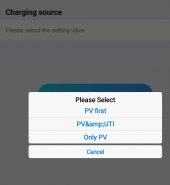
Maybe this is the setting? PV&UTI
I don't see any setting regarding setting the amp value to start utility assist?
Screenshot_20221114-222952_ShinePhone.jpg
 
Last edited:
I thought that if my inverter uses more than 200A for 2 minutes, the BMS will trip and I will switch to grid bypass abruptly.

Will the BMS comm tell the inverter to split the load with the grid when it goes over 200A
The BMS will trip after 30 seconds(default setting) if the inverter pulls more current than the max OCP setting in the BMS.

My code will advise the inverter of the Max discharge current it can use, the inverter "should" do what the battery asks, eg only pull 200A.
What the inverter does after this depends on the inverter and how it is configured.

My inverter is AC coupled onto the house mains, so it delivers as much power as it can (following the house demand and max battery discharge current) anything over and above comes from the grid, it's 5kW output so not very often do we exceed it, but I don't have an EV to charge.
 
I have SPF-12000T Growatt and just purchased a couple EG4s.
So that inverter seems to be marketed as an off grid inverter and seems to have grid charging/bypass, it's not Grid interactive.
Max 120A charging from solar, max 100A from grid, combined max charging 180A
There is no mention of discharge current from the battery how they can produce a spec sheet and not detail the discharge current is beyond me lol
200A discharge would limit it to around 10kW, you probably don't want to run it at 100% for any length of time, so that's probably a good thing.
 
Last edited:
I also have 3x jk bms in paralell. Would be cool if we could have 1xesp32 for each bms and set an id here and send them all to another esp32 witch convert all the data to can.
 
Edit. Issent that how pylontech batterys work? You Just set an id on each battery?

So if we have 3 esp32 with canbus sender for each battery. If we Just are avle to set an id for each pack they can be paralelled?
 
Issent that how pylontech batterys work?
Pylontech have multiple interfaces, they are all connected together with link ports(rs485?), the master communicates to the inverter using the CAN port.

That would be a different architecture to how it currently works.
If you just connected ESP32's to each BMS they will all be trying to communicate with the inverter, which would just cause chaos.
There is currently no way to link the esp32s and have a master communicate with the inverter.

It sounds simple but in reality there would have to me a major re-architect and rewrite to facilitate it.
I simply don't have the hardware required(second set of batteries and BMS) to even start looking at it.
I understand. Mabey I can contribute later :)
 
Where do we set the maximum charging current?
In the released version the charging current is set to the jk-bms charging_overcurrent_protection value.

In the new version I'm about to release it is controlled by config file and Slider controls in homeassistant, see my post in page 3.
 
In the released version the charging current is set to the jk-bms charging_overcurrent_protection value.

In the new version I'm about to release it is controlled by config file and Slider controls in homeassistant, see my post in page 3.
What's the expected released date.
 
What's the expected released date.
I have released the new version:

V1.11 4/12/22
Tested on ESPHome Version: 2022.11.4, upgrade by running "pip3 install -U esphome"

Complete rework of the charging logic, now charges with constant current(CC) to the absorption voltage, then has an absorption timer (Constant Voltage, user configurable time), with rebulk feature (user configurable offset from absorption voltage).
Live sliders for absorption voltage and charging current (can change on the fly!)
Charging status user feedback to let you know what the charging logic is doing. Bulk, Absorption, Wait , Disabled, etc
Reworked the Charge/Discharge controls and logic, so more user friendly (default to on as below).
  • Battery control switches to manage battery remotely
    • Charging request status
    • Absorption voltage (slider)
    • Charging current max (slider)
    • Charging enabled/disabled
    • Discharging enabled/disabled
    • Charging manually (top balancing)

1668323326808-png.120009
 
Last edited:
I have released the new version:

V1.11 4/12/22
Tested on ESPHome Version: 2022.11.4, upgrade by running "pip3 install -U esphome"

Complete rework of the charging logic, now charges with constant current(CC) to the absorption voltage, then has an absorption timer (Constant Voltage, user configurable time), with rebulk feature (user configurable offset from absorption voltage).
Live sliders for absorption voltage and charging current (can change on the fly!)
Charging status user feedback to let you know what the charging logic is doing. Bulk, Absorption, Wait , Disabled, etc
Reworked the Charge/Discharge controls and logic, so more user friendly (default to on as below).
  • Battery control switches to manage battery remotely
    • Charging request status
    • Absorption voltage (slider)
    • Charging current max (slider)
    • Charging enabled/disabled
    • Discharging enabled/disabled
    • Charging manually (top balancing)

1668323326808-png.120009
Thanks. I have updated.
What is the effect of changing this line in the yaml file batt_modules: "3"?
If someone is using 16 pieces of 280AH and sets this to 1 and another person with same batteries sets it to 5, what will be the expected outcome?
Does it affect charging current?
 
Back
Top