


I am waiting for my devkit and TJA1050 to arrive to use this your wonderful app. Thanks once again for making this open source.
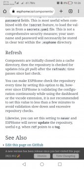
Please just one observation: the external component is set to refresh every now and then as against recommended minimum of a minute. What does this entail? Won't it be drain on the resources if it keeps checking like this? What is the implication if one sets it to NEVER?
It appears you are working on Bluetooth support as well.
Thanks

")