diy solar

diy solar

The Electrodacus SBMS thread (SBMS0, DSSR50, etc)

This whole concept has blown my mind!!!

What I can't quite get my head around is the unregulated voltage to the expensive LifePo4 cells

5.55 / 4 = 1.3875V additional voltage per cell which is a 38% possible increase in charge voltage!!!!!

I get that the stated Vm is unlikely but what damage is possible. How is the SBMS0 protecting my cells against this, is it just by cutting the power via the DSSR20 when voltage is above a specification set in the parameters.
I could be wrong, but....

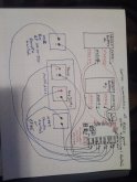
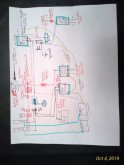
The LiFePo4 cells have near zero resistance, this means that they are basically determining the voltage not the panel. Sure, the panel has an open circuit voltage that is too high and Vm is too high too, but the batteries drag that down to their 14.4v (don't quote that value, don't use that value).

The fact that the panel is not at Vm, means the panel is not delivering maximum power that it could. If the batteries would leave the voltage at 19.95v, then the watts would be maxed. This is why I believe Dacien recommends finding 30 cell, for 12v, or 60 cell for 24v panels. They will have a Vm closer to the batteries.

The MPPT sets the voltage from the cells to Vm and delivers the right voltage to the batteries, thus the MPPT is a DC/DC converter that requires a bunch of expensive parts.

The SBMS0 cuts off the panels when the voltage climbs above the 14.4 (or whatever, again don't quote me) because that indicates the batteries are getting full. (Or it can watch the state of charge and cut off at your favorite % if you like).
 
Alright, I'm starting to look into comparative real world tests between MPPT and PWN, I came across this test from a source I have a lot of respect for. Its not exhaustive but over a 7 day period in the Maine spring, 21% efficiency gain was observed with MPPT. Its worth reading, there is a good intro to the theory as well as the test results.
...
Right, but the problem is how to determine that you will gain anything that makes a difference to you.

I live in Seattle WA and I have a 36' RV. This is exactly the situation that begs for an MPPT. The panels at the front will be nearly 50ft from the original battery location. I can fit 2kw of panels and not really an ounce more.... unless I got some deployable ones. If this isn't limited space, lousy sunshine, and long cables, I don't know what is.

But, wait, no amount of MPPT, ZPW, or PQZ will give me enough sun to run much at all in the winter. My wife said to me on Mar 1 (don't quote me on the exact dates), "Oh, look we have the first sunshine since October!". I trashed my AGMs when I left the power on in the winter for a week. The passive loads were like 2amps (50watts). The batteries were at 10% when I realized my mistake. At that time I had 800watts of panels on the roof.

Since then I have doubled to 1.6kw of panels and I have whacked out some passive loads. Am I certain that I can live through that sun drought and not turn on the generator? If the MPPT would make the difference between having the generator and getting rid of it, then yea, I'll take the MPPT. If I have the generator, then what is the point of the MPPT? For the bulk of the year, I'm throwing away a ton of power.

The cable issue is a bogus thing. When we are struggling to eeek out the last ounces of sun to keep from turning on the generator, then the cables are not moving any significant amps. 14 gauge wire will do the trick. When the sun is out, you have too much power, so it makes no difference that there is a large heat loss in those dinky wires.

In the end, it isn't measurable what I will get from the MPPT. Sure, you can set up a scenario in Maine and get 20%. But does that 20% take me across the threshold of having enough power in the dregs of winter, and will I get that 20%?

I hate spending more if I cannot quantify it. My brother keeps telling me that cheap tools are a waste of money. The problem is that he never told me how to identify a cheap tool vs a good bargain. He only told me how to spend more $.
 
I think one of the things that needs factoring into this is panel angle.

Its much easier to angle panels for optimum PV in a fixed array, on a vehicle its very difficult to do anything other than flat.

My conclusion at this point is that this Solar Battery Management System is better for fixed arrays
  • Fixed arrays typically require one-time large investment in solar panels & batteries
  • The array and battery bank can be optimised for location and weather
  • The investment is long term due to large cost of capital items
MPPT appears to me to work better for mobile applications:
  • Due to limited roof space typically small array to battery ratio
  • Flat panels reduce array efficiency so less hours of suitable solar generation
  • Array can be subject to many different location and weather variables including shading
  • PV to battery power needs to be optimised due to inefficencies above
  • Investment is shorter term due to smaller lower capital investment & typical vehicle life
What I love most about the SBMS0 is the data collection :love:

I tend to agree with your analysis here (the only thing I would clarify is that your analysis is really more about the DSSR20 than the SBMS0 (which can be used with either the DSSR or MPPT).

Many of the points you make re: MPPT are not considered by Dacian (in his videos, manual, etc) as they are outside of his model. And are the same reasons that I can both agree with Dacian's argument that MPPT no longer makes economic sense in most contexts, while still preferring MPPT for my use-case.

Unpredictable partial shade being a primary consideration for me (also why I'm leaning towards multiple small MPPT controllers).


It makes sense that Dacian's model wouldn't account for a lot of the factors you outlined since the SBMS is somewhat of a hobby project originally developed to meet his needs for his offgrid home, and was originally modeled around a very high ratio of PV to Battery, 20+ year system life, and no space constraints.

And considering that this is where he lives:
dacian-house.png

I don't think shade or space are of much concern out in the endless expanse of the Canadian plains :LOL:


All that said, I don't think the DSSR20 is a bad choice for vehicles (especially if dead simple reliability is a priority), I just think that its probably not quite as competitive with MPPT as it is in the context that Dacian designed it for.

I do hope that someone (cough cough @Dhowman maybe) will beg, borrow, or buy, a Victron MPPT and do some real world comparison testing!

Once I move from the design to purchasing stage of my project I might, but that might still be a year or two off.
 
Last edited:
If you are using or planning to use the SBMS0 and you have sketched out a diagram or schematic, or have pictures of your setup please share it here. We are a small group of folks using or planning to use this BMS, and there isn't much info on it available online, if we can get a handful of examples in one place, it'll go a long way to helping others with their designs, and we can learn and borrow from eachother!
 
If you are using or planning to use the SBMS0 and you have sketched out a diagram or schematic, or have pictures of your setup please share it here. We are a small group of folks using or planning to use this BMS, and there isn't much info on it available online, if we can get a handful of examples in one place, it'll go a long way to helping others with their designs, and we can learn and borrow from eachother!
I am using 2 SBMS0s for a 24 volt 2 Tesla Module system. I use a Victron Multiplus 24/3000 70-50, 1150 watts PV connected to a Epever 40 amp MPPT.
Tom
 

Attachments

  • P_20200313_185809.jpg
    P_20200313_185809.jpg
    90.4 KB · Views: 38
  • P_20191004_194141_p.jpg
    P_20191004_194141_p.jpg
    90.7 KB · Views: 39
  • Like
Reactions: Dzl
To start things off,

Here is a very early working draft of the system I am designing. It is very likely that there are errors and omissions, and very likely that it will change substantially between now and the final version.


This is a vehicle based system. Some of my guiding design principles/objectives are:
  • Maximum efficiency
  • Minimal no-load consumption
  • Modularity
  • Maximize partial Shade tolerance/performance
  • Flexible/wide range of operation
  • Open Source, Open Hardware, and DIY where possible
  • Layered protection and control
  • Data! I ❤ pretty charts and graphs :)
  • And of course cost/value

Edit: I also made a diagram to make sense of my diagram (not even joking... :LOL:), in case the full diagram is too overwhelming cluttered. The basic layout is Top: charge sources, Middle: battery core system + primary distribution, Bottom: load distribution.
schematic-map.png
 
Last edited:
To start things off,

Here is a very early working draft of the system I am designing. It is very likely that there are errors and omissions, and very likely that it will change substantially between now and the final version.


This is a vehicle based system. Some of my guiding design principles/objectives are:
  • Maximum efficiency
  • Minimal no-load consumption
  • Modularity
  • Maximize partial Shade tolerance/performance
  • Flexible/wide range of operation
  • Open Source, Open Hardware, and DIY where possible
  • Layered protection and control
  • Data! I ❤ pretty charts and graphs :)
  • And of course cost/value
Nice drawing. What tool did you use to create it ?
 
I am using 2 SBMS0s for a 24 volt 2 Tesla Module system. I use a Victron Multiplus 24/3000 70-50, 1150 watts PV connected to a Epever 40 amp MPPT.
Tom

Thank you! Super helpful, I need some time to digest though

P_20200313_185809.jpg

P_20191004_194141_p.jpg
 
To start things off,

Here is a very early working draft of the system I am designing. It is very likely that there are errors and omissions, and very likely that it will change substantially between now and the final version.


This is a vehicle based system. Some of my guiding design principles/objectives are:
  • Maximum efficiency
  • Minimal no-load consumption
  • Modularity
  • Maximize partial Shade tolerance/performance
  • Flexible/wide range of operation
  • Open Source, Open Hardware, and DIY where possible
  • Layered protection and control
  • Data! I ❤ pretty charts and graphs :)
  • And of course cost/value
Are there any problems associated with connecting/disconnecting via relay the batteries from the MPPT SCCs?

Why use several MPPT SCCs?

Again super neat drawing (y) what software did you use?
 
Nice drawing. What tool did you use to create it ?

Diagram created with Draw.io, its my first time using it but I really like it so far. Its pretty easy to work with having layers is great, putting each module or circuit in its own layer adds a lot of flexibility, and makes it easier to focus on just the relevant components. For example, the diagram I posted above has all the layers but its pretty cluttered, with just a few clicks I can see:

dzl_alpha_draft_02-alt(4).png
Or
dzl_alpha_draft_02-alt(6).png
The individual components were either borrowed and modified from other diagrams (especially Victron's) or created in GIMP (free open source photoshop like program).
 
Last edited:
Are there any problems associated with connecting/disconnecting via relay the batteries from the MPPT SCCs?

So I suppose there are two questions embedded in this question:

First, is it safe for the battery protect to be used in this manner?

As far as I know, this is as acceptable but non-conventional way to use the battery protect (see this thread) more specifically @Justin Laureltec's response. But its something I would confirm with Victron before moving forward if I stick with this design.

Second, is it safe for the charge controllers to be disconnected from the battery while connected to the PV panels?

Conventional wisdom not so long ago was that this was not a good idea. However, this perception seems to be shifting (see Will's thread "Trying to destroy my SCC's, I can't") Victron's documentation doesn't caution against this or otherwise indicate that this is a bad idea or would void their warranty. See post #42 and #43 for more info and a good explanation from Justin, that pretty much puts the issue to rest in my eyes, at least with Victron controllers.


Why use several MPPT SCCs

This is a practice seen mostly in the marine world where rigging, sails, etc can really screw with solar output. I'm incorporating it as part of my strategy to mitigate partial and unpredictable shading. 1:1 panel to MPPT ratio means partial shade on 1 panel has no effect on the others, and each controller can determine the maximum power point specific to the panel hooked up to it. I understand the theoretical benefits of this, I have no idea what the real world gains will be, and haven't been able to find much data on it, but its often recommended in the marine world and the difference in price between 3 small controllers or 1 larger controller is pretty negligible ($355 for 3x 75v/15a, or $325 for 1 x 100v/50a) so I'm willing to pay a little more for the theoretical benefits.

Its part of my broader attempt to mitigate partial shade
  1. Use panels designed to perform better in partial shade (like REC Peak or Alpha panels or Sunpower X series or P series)
  2. Use higher voltage panels and minimize or eliminate series connections
  3. Multiple MPPT controllers
  4. Possibly make one of the 3 solar 'modules' portable so if I'm camped in the shade I can set up one module in the sun away from the vehicle. Probable won't end up doing this, but its an option.
If you, or anyone else is interested, I have started several threads (see here) on partial shade performance, as questions have come up and as I've learned.


As I mentioned, this is a super early working draft of the system I'm designing, so a lot will probably change, and I very much welcome questions, criticism, tire kicking, recommendations, and second guessing :)
 
Last edited:
So I suppose there are two questions embedded in this question:

First, is it safe for the battery protect to be used in this manner?

As far as I know, this is as acceptable but non-conventional way to use the battery protect (see this thread) more specifically @Justin Laureltec's response. But its something I would confirm with Victron before moving forward if I stick with this design.

Second, is it safe for the charge controllers to be disconnected from the battery while connected to the PV panels?

Conventional wisdom not so long ago was that this was not a good idea. However, this perception seems to be shifting (see Will's thread "Trying to destroy my SCC's, I can't") Victron's documentation doesn't caution against this or otherwise indicate that this is a bad idea or would void their warranty. See post #42 and #43 for more info and a good explanation from Justin, that pretty much puts the issue to rest in my eyes, at least with Victron controllers.
I agree. Some SCCs, and even SBMSn where n>0 ... you cannot disconnect battery before you disconnect panels. Well, you could, but you fry the SCC. I do not believe this is true with Victron MPPT. Peeps do this all the time with them (and other SCCs) to no ill effect. Def worth confirming if this is possible for your specific model before doing this.
This is a practice seen mostly in the marine world where rigging, sails, etc can really screw with solar output. I'm incorporating it as part of my strategy to mitigate partial and unpredictable shading. 1:1 panel to MPPT ratio means partial shade on 1 panel has no effect on the others, and each controller can determine the maximum power point specific to the panel hooked up to it. I understand the theoretical benefits of this, I have no idea what the real world gains will be, and haven't been able to find much data on it, but its often recommended in the marine world and the difference in price between 3 small controllers or 1 larger controller is pretty negligible ($355 for 3x 75v/15a, or $325 for 1 x 100v/50a) so I'm willing to pay a little more for the theoretical benefits.

Its part of my broader attempt to mitigate partial shade
  1. Use panels designed to perform better in partial shade (like REC Peak or Alpha panels or Sunpower X series or P series)
  2. Use higher voltage panels and minimize or eliminate series connections
  3. Multiple MPPT controllers
  4. Possibly make one of the 3 solar 'modules' portable so if I'm camped in the shade I can set up one module in the sun away from the vehicle. Probable won't end up doing this, but its an option.
If you, or anyone else is interested, I have started several threads (see here) on partial shade performance, as questions have come up and as I've learned.


As I mentioned, this is a super early working draft of the system I'm designing, so a lot will probably change, and I very much welcome questions, criticism, tire kicking, recommendations, and second guessing :)
So, a few things jump out at first glance:

1. Maybe I'm missing something, but I don't see how paralleling 3 panel/mppt combos is any different than paralleling 3 panels to one larger MPPT when it comes to shading. Sum of the 3 smaller power points would be equal to the power point of the one larger one, no? And total amps produced by those 3 panels and seen by 3 MPPTs isn't gonna be different than what one MPPT sees regardless of how much or how little shade is hitting them. And if that larger one had remote on/off, you don't need the BP. Only advantage I see is that if that one MPPT has a problem, you have no solar. You have some redundancy with the 3-MPPT setup.

2. Also, just want to make sure you know that you've defeated the isolation of your DC-DC charger by grounding your NEG bus to chassis. It's, essentially, a non-isolated DC to DC charger at that point. Not sure what the ramifications (or benefit) of doing that is, esp if you eventually hook all that up to a generator or shore power too and have everything running at the same time.

3. Also, what's the use case for 2 BPs on your DC loads line (w 2-24V and 2-12V DC panels = 4 distribution panels)? What's controlling the 2nd one to your "Switched Distribution?" "Unswitched Distribution" is switched by the first BP, is it not?

4. Why the fuse/switch combos? Why not just breakers performing both functions? One switch for everything coming to the battery shunt? You might want the flexibility of having breakers on all those individual lines (vs one switch/multiple fuses).

Overall, it seems, maybe, that the total # of devices here could be minimized to make for a simpler/easier to troubleshoot system that satisfies the same requirements. Or maybe I just don't understand the requirements part well enough.
 
Last edited:
1. Maybe I'm missing something, but I don't see how paralleling 3 panel/mppt combos is any different than paralleling 3 panels to one larger MPPT when it comes to shading. Sum of the 3 smaller power points would be equal to the power point of the one larger one, no? And total amps produced by those 3 panels and seen by 3 MPPTs isn't gonna be different than what one MPPT sees regardless of how much or how little shade is hitting them. And if that larger one had remote on/off, you don't need the BP. Only advantage I see is that if that one MPPT has a problem, you have no solar. You have some redundancy with the 3-MPPT setup.
Caveat to this is, if your panels aren't all the same voltage, you could benefit by matching w multiple/different MPPTs.
 
I love this! Feedback like this is why I love this forum. All very good points and questions. You've touched on a lot of points that I've gone back and forth on, and highlighted isssues I hadn't fully considered. I'm not going to respond to it all here as I don't want to distract from the focus of this thread, but I started this thread here to discuss and explain my design as it evolves, and I'll address the points you made here in that thread.
 
Really feel Dacian is missing an increasing market, by not offering a 48v version. As things head to 'all electric' the world over, larger battery banks are going to be sought. :-(

The point is Kernel, this guy is onto something with this design....extending the range has the potential to open up whole new markets to him. Maybe he is simply happy with production as is....something to be said of stay small, stay in control.

I'm dragging up an old part of the conversation, but I came across more explanation as to why Dacian has not built a 48V version in the comments section of wills video on the SBMS0.

somebody on youtube said:
The product, help and support are excellent but like most setting up an off-grid home system and integrating it with victron products not supporting 48V has meant that non of his products are usable. All the other big solar mppt/inverter manufacturers would all be 48V in an off-grid house application. So disappointing!

Dacian said:
I do not design anything that exceeds 50V DC open circuit voltage for safety reason and to stay in the Low voltage standard that is set at 50 or 60V DC around the world. As SBMS0 can handle 750A and can deal with up to 30kW PV array I do not see a limitation in most systems. I even fully heat my house with 24 to 30V DC system so there is not a big advantage to 48V other that some savings on wires but that from the total cost of the system is not much and the extra safety of lower voltage is worth it for me. I designed this for my own use I'm not in any way a big manufacturer is more of a hobby. I do understand that you are already invested in 48V so you need to stay with that. Tow SBMS0 in series can control a 48V system but is not at all an elegant solution so not something I recommend.
 
Couple new youtube videos on the SBMS0:


Liked the 2nd vid. First one I've seen that included DSSR20 in the demo. First vid was a little distracting, worrying he was going to stand up. #pants? lol
 
  • Like
Reactions: Dzl
Hey Folks, I got inspired by the schematic that DZL posted about using the SBMS0 on a 24V off grid system. I'm planning something similar, spit 12-24V system, but on a sailboat. Would very much welcome comment and criticism on my "alpha" schematic... See the pdf if the zoom sucks. Thanks everyone!
James SBMS0 Aplha Schematic.png
 

Attachments

  • James SBMS0 Aplha Schematic.pdf
    4.7 MB · Views: 36
  • Like
Reactions: Dzl
Hey Folks, I got inspired by the schematic that DZL posted about using the SBMS0 on a 24V off grid system. I'm planning something similar, spit 12-24V system, but on a sailboat. Would very much welcome comment and criticism on my "alpha" schematic... See the pdf if the zoom sucks. Thanks everyone!
View attachment 11802

Looks good at first glance!

You may want to consider locating a fuse on the positive line where it branches off just before the solar shunt, depending on the distance between that point and the branch fuses after the switch. I'm not necessarily recommending it and i'm far from an expert, but it is something I would be considering. You do have the MRBF fuse on your main battery negative, so the fuse on the + side maybe isn't exactly necessary, my design has the fuse on the negative as well, but I"m still not 100% comfortable with that arrangement personally.

You might also want to double check ABYC code (if you are located in the US), it requires a fuse within 7" of the battery, there are a couple exceptions to this. I'm not sure if fusing the negative side meets this rule or not.

Otherwise, looks good.

What 24v to 12v converters are you using?
 
Back
Top