diy solar

diy solar

Request for comment, criticism, questions, tire kicking, and musing (early alpha system design)

Dzl

Unofficial Forum Librarian & Perpetual Newbie
Staff member
Moderator
Joined
Dec 10, 2019
Messages
5,108
Location
West of the rockies
What this isn't: Set in stone, finalized, error free, or complete. Tthis is not a request to double check my numbers or little technical details (though that is welcome), much will change before I arrive at my eventual final system design, and many of the details are yet to be decided. I welcome and ecourage your feedback, criticism, and questions on issues big and small, nothing is off limits, and general tire kicking and pondering is encouraged as well.

What this is: The diagram below is the first early draft of my proposed system. It is probably one of a handful I will create which will reflect different approaches and evolve as I continue to learn and rethink. I'm a visual learner, so getting everything down on 'paper' is part of the process and helps me rethink and iterate and understand. This is an early draft and I'm still a relative newbie, there are undoubtedly mistakes and things I will change (point them out where you see them).

How to interpret this diagram:
The general layout is that the core system (battery, bms, positive and negative busbars) is in the middle, charge sources are at the top, and AC and DC loads are at the bottom.

A note on the DC distribituion:
The DC distribution is a bit overcomplicated and is probably in need of some revision. But there is a logic to it. What complicates things is that the system is 24V with both 12 and 24 volt consumers (my goal is mostly 24v), and two 'levels' or 'layers' of DC distribution. In the diagram this is referred to as 'unswitched' and 'switched' distribution (a concept borrowed from Pacific Yacht Systems) but you could also think of this as 'critical' and 'non-critical' loads.
  • The unswitched loads will be things like safety devices, the fridge, and other devices that are intended to always have power in normal conditions. The BMS will still be able to cut power to these circuits (via a smart battery protect), but it is the safety device of last resort and shouldn't cut power in normal conditions.
  • A second smart battery protect will control the switched loads. This enables more granular control (manual and automated) of non-critical loads. Manually it makes it really easy to switch off all non-critical loads with the flip of a switch (physical or from the Victron App) if I'm leaving the vehicle for a few days or for various other reasons. It also means that non-critical loads can be disconnected earlier (at a higher SOC) than the point at which the BMS disconnects all loads which could substantially increase my time of autonomy in poor solar conditions.
Unfortunately, switched and unswitched x 12v and 24v means 4 separate DC distribution blocks, which is a little ridiculous ?, but I like concept. I am still considering either switching the system to 12v only, or ditching the switched and unswitched concept. I'd like to hear your thoughts!

My Use Case and Goals: This is a mobile (vehicle based) design. 70/30 on-pavement/off-pavement, mostly full-time lived in, mostly or completely off-grid, solar is the primary power source.

Some of my guiding design principles/objectives are:
  • Maximize efficiency
  • Minimal no-load consumption
  • Modular
  • Maximize partial Shade tolerance/performance
  • Flexible/wide range of operation
  • Open Source, Open Hardware, and DIY where possible
  • Layered protection and control
  • Data! I ❤ pretty charts and graphs :)
  • And of course cost/value

System Overview (Draft):

z3Iob9V.png


Core System Conceptual Closeup:

fHk6Qyv.png
 
Is it possible that the mrbf fuse blocks could swivel on the busbar posts and touch each other?
 
Is there a BMS on the battery?

Yes, the SBMS0 (to the left of the battery in the top image) is the BMS. Unlike other BMS' it doesn't sit between the battery and the chargers/loads, it sits outside the circuit and controls charge/discharge indirectly by remotely controlling the individual components via remote on/off.
 
Is it possible that the mrbf fuse blocks could swivel on the busbar posts and touch each other?

This is a very good point that I hadn't even remotely considered. That is entirely possible, I think it wouldn't be too hard to eliminate that risk if designed right though.

My inspiration for this design comes from this Victron schematic, the Victron Lynx, and this DIY busbar/fuse/switch combo from explorist.life. All use ANL type fuses, I hadn't considered how the MRBF form factor would change things. I think its a solveable problem, but definitely needs to be considered in the design.

It's also worth noting I'm still going back and forth on whether to use MRBF fuses, breakers, or something else.
 
Was thinking about this from the previous thread

I’m sure I’ve seen some SCC don’t like having batteries disconnected

a much better solution would be to use the SBMS0 to control the Victron SCC as designed. This would manage it correctly and not risk the devices

Also connecting the solar panels in parallel and into just one device would achieve the same goal as the current multiple device set up.

If multiple SSCs are used the SBMS0 could probably control them via the same control wire
 
Hey! I appreciate the feedback/questions, you bring up some good points, I'll do my best to explain my reasoning.

I'm splititng my response into two comments.

First: Is it safe to disconnect a Victron Charge Controller from the battery without disconnecting it from PV first?

Was thinking about this from the previous thread

I’m sure I’ve seen some SCC don’t like having batteries disconnected

a much better solution would be to use the SBMS0 to control the Victron SCC as designed. This would manage it correctly and not risk the devices

You may be right with some controllers, I don't know. But with Victron controllers, this issue has been put to rest in my mind. Not sure if you saw my explanation in the Solar BMS thread, or clicked through and read @Justin Laureltec's answer to my question to my question.

DZL said:
Can anyone (@Justin Laureltec maybe) clarify whether Victron specifically cautions against or prohibits placing breakers or switches between the battery & SCC?
Can confirm that they don't actually care, and in fact require a fuse or breaker between the SCC and the battery. Technically the wording is in there because of a conceptual problem on paper that they wanted to make sure would never happen, but this was written before the days of LFP and BMS systems and all that. Their own systems now will shut off the battery when necessary, which would obviously create the very problem that they're trying to -theoretically- avoid.

I too have tried really hard to make a Victron SCC fail in this way, under various conditions including the full-bore-charging sudden disconnection event that the wording was theoretically written to avoid, and I have never managed to cause a problem by doing this.

The official word from Matthijs [CEO at Victron] on this is that no one has ever heard of this condition actually causing a problem, it's just that an engineer back when his dad was originally developing these decided to include the language to cover for a theoretical problem that has never, in anyone's experience, actually occurred. With that in mind, they've been going through and slowly updating manuals accordingly... there definitely used to be some stronger language in the manuals that's now being removed (can't guarantee it's out of all the manuals yet) with only the language about connecting the battery first being left in - and that's just so the units can recognize and set the system voltage.

Switching the SCC directly is an option, but so is switching a battery protect (both are explicitly referenced in the SBMS0 manual). If I go a single charge controller that has remote on/off this is what I will do, but its easier to go the SBP route if I use multiple controllers, and I see no reason not to.

If you think about it, what I am doing would be no different in outcome than a Chargery BMS cutting off charging via a mechanical relay, or a Daly BMS cutting off charging internally, or a fuse or breaker blowing between the battery and SCC. In each case, the SCC is disconnected from the battery while still connected to the PV array.
 
Last edited:
Second: Why am I using multiple MPPT charge controllers

Also connecting the solar panels in parallel and into just one device would achieve the same goal as the current multiple device set up.

Partially, yes. Multiple MPPT serves two purposes (1) like parallel panels, it means that shade on one panel will not affect the output of the others (2) Each SCC can independently calculate the maximum power point for the specific conditions of the panel it controls. MPPT controllers are most efficient under uniform solar conditions (1) (2). Two use cases where you see multiple MPPT controllers used are on sailboats and on split east-west facing PV arrays. Also solar panel optimizer are based on the same logic (per panel mpp calculation)

I'm a bit out of my depth talking about this last point, its an accepted practice in the marine world, and this is one place that I've just trusted that there is a reason for this without taking the time to fully understand it. And honestly I have no idea whether the improvement would be 2% or 20%. But I don't see any compelling reason not to go that route since the cost difference is pretty negligible, and I do know that marine electrical outfits like Pacific Yacht Systems recommend one MPPT per panel for maximum shade tolerance.

I believe that the basic premise in laymens terms is that the maximum power point is a product of voltage and current, with a PV panel voltage fluctuates based on the amount of light (solar irradiance) hitting the panel, shade reduces the amount of light hitting the panel, and thus shade affects the maximum power point. Because shading conditions will be different across an array multiple mppt controllers or optimizers will be able to more efficiently calculate maximum power point. This is my best attempt at articulating what I think the logic is, but I can't stress enough how think my knowledge is on this particular topic. @BiduleOhm I believe you have commented on this subject in the past, can you provide any input?

This is definitely an area where I am hoping to deepen my understanding, beginning with the fundamentals of maximum power point calculations.

If any of this is still not making sense to you (or you think I'm misunderstanding something) I appreciate the questions, and the pushback, and being made to try to explain my decisions. It helps me learn and exposes the flaws in my logic and the gaps in my knowledge, so keep it comin':)
 
@Dhowman made some very good points in another thread, I want to address those here:

Dhowman said:
1. Maybe I'm missing something, but I don't see how paralleling 3 panel/mppt combos is any different than paralleling 3 panels to one larger MPPT when it comes to shading. Sum of the 3 smaller power points would be equal to the power point of the one larger one, no? And total amps produced by those 3 panels and seen by 3 MPPTs isn't gonna be different than what one MPPT sees regardless of how much or how little shade is hitting them. And if that larger one had remote on/off, you don't need the BP. Only advantage I see is that if that one MPPT has a problem, you have no solar. You have some redundancy with the 3-MPPT setup.

I think that you are missing something, unfortunately I'm not knowledgeable enough to clearly articulate it (see my previous comment for my best attempt).

The long and short of it is that MPPT is most efficient when solar irradiance is uniform across an array, the MPP is a calculation based on current and voltage, current [edit: voltage] will be roughly the same for a PV panel, but voltage [edit: current] will change based on the amount of light hitting the panel, so shade will lower the voltage, ideally the maximum power point is adjusted to reflect that, but if different amounts of light are reaching different parts of the array and there is only one controller, it can't deliver the maximum power point for both the shaded and unshaded panels.

I do wish I could find some actual data (real world or theoretical) as to how big of an effect this could have.

Dhowman said:
2. Also, just want to make sure you know that you've defeated the isolation of your DC-DC charger by grounding your NEG bus to chassis. It's, essentially, a non-isolated DC to DC charger at that point. Not sure what the ramifications (or benefit) of doing that is, esp if you eventually hook all that up to a generator or shore power too and have everything running at the same time.

Correct. What your looking at is my indecision on whether to go isolated or non-isolated, I'm leaning towards non-isolated (but still have a lot more learning to do before I'm confident in my decision). The wiring reflects this (non-isolated) with the exception of the DC-DC charge circuit where I stuck the isolated version in as a placeholder. I remember Justin saying in another thread that the only effect of using the isolated charger in a non-isolated system was that it would just be a non-isolated charger that cost more $$. Once I get my ducks in a row here, I'll modify the diagram and update the wiring. If I choose to go isolated, I believe the only change I would need to make to the diagram is removing the chassis ground at the negative busbar, and the negative wire between the B2B and the starter battery, does that sound right to you?

Dhowman said:
3. Also, what's the use case for 2 BPs on your DC loads line (w 2-24V and 2-12V DC panels = 4 distribution panels)? What's controlling the 2nd one to your "Switched Distribution?" "Unswitched Distribution" is switched by the first BP, is it not?

Covered in the original post of this thread. In short I agree,
  1. The ridiculousness of 4 fuse blocks is not lost on me ? . 4 fuse blocks on the diagram won't actually be 4 actual fuse blocks in real life, it just represents that there will be 12 and 24 volt circuits in both the switched and unswitched groups.
  2. The ridiculousness of the terms 'switched' and 'unswitched' in a system where everything is switched is also not lost on me, but for lack of better terms and because the place I borrowed the concept from used these terms, I stuck with them :).
  3. I explained the use-case above, but briefly, it allows more granular, automated and manual control.
  4. I'm actively looking at ways to reduce this complexity including ditching the switched/unswitched concept, moving to 12v batteries, or moving to a single 24v to 12v converter upstream of switched and unswitched distribution. Any of these solutions would halve the complexity and maybe save some money.

Dhowman said:
4. Why the fuse/switch combos? Why not just breakers performing both functions? One switch for everything coming to the battery shunt? You might want the flexibility of having breakers on all those individual lines (vs one switch/multiple fuses).

This is something I have gone back and forth on. My earliest design did use breakers, and honestly I would still kinda prefer to use them. There are a couple reasons my current design uses fuses:

  1. Cost, MRBF fuses are relatively cheap compared with the breakers I was looking at. Fuses + Switch saved about $100 over the cost of breakers.
  2. Form, Super easy to integrate the MRBF fuse holders onto a busbar, which is what I plan to do.
  3. High Interrupt Capacity (roughly double that of the bussman / blue sea breaker I was looking at which didn't meet ABYC standards (these are marine standards but I'm using them as a general reference) for main battery overcurrent protection which is 5000A for a 24v system). I changed from these breakers to fuses when I learned the SBMS0 was incompatible with a main fuse on the + post, I'm still on the fence about putting the fuse on the - post. If you (or if anyone else) has a recommendation for affordable breakers well suited for main battery circuit protection I would be grateful for the reccomendation, my knowledge here is limited.


Dhowman said:
Overall, it seems, maybe, that the total # of devices here could be minimized to make for a simpler/easier to troubleshoot system that satisfies the same requirements. Or maybe I just don't understand the requirements part well enough.

Truer words have never been said! I have a tendency to over-design.. I like my design, but its also more complicated than it needs to be, there are advantages to this, but also more potential points of failure, and more potential points of confusion. I definitely tend towards overdesigning stuff, especially early in the process. Down the road in later drafts, I'll start focusing more on simplifying, cutting costs, and cutting complexity.

At this stage, I'm kinda trying out the concepts I've been mulling over in my head, seeing how it all fits together and what it looks like on paper, I'm a visual learner, so drawing it all out is part of the process for me.

Again, I really appreciate the feedback, and questions, and pushback, and I've learned a lot from your design threads, so I appreciate you taking the time to provide your thoughts and constructive criticism. I've already begun rethinking some things based on the feedback from you and others so far.
 
Last edited:
Partially, yes. Multiple MPPT serves two purposes (1) like parallel panels, it means that shade on one panel will not affect the output of the others (2) Each SCC can independently calculate the maximum power point for the specific conditions of the panel it controls. MPPT controllers are most efficient under uniform solar conditions (1) (2). Two use cases where you see multiple MPPT controllers used are on sailboats and on split east-west facing PV arrays. Also solar panel optimizer are based on the same logic (per panel mpp calculation)

I'm a bit out of my depth talking about this last point, its an accepted practice in the marine world, and this is one place that I've just trusted that there is a reason for this without taking the time to fully understand it. And honestly I have no idea whether the improvement would be 2% or 20%. But I don't see any compelling reason not to go that route since the cost difference is pretty negligible, and I do know that marine electrical outfits like Pacific Yacht Systems recommend one MPPT per panel for maximum shade tolerance.

I believe that the basic premise in laymens terms is that the maximum power point is a product of voltage and current, with a PV panel voltage fluctuates based on the amount of light (solar irradiance) hitting the panel, shade reduces the amount of light hitting the panel, and thus shade affects the maximum power point. Because shading conditions will be different across an array multiple mppt controllers or optimizers will be able to more efficiently calculate maximum power point. This is my best attempt at articulating what I think the logic is, but I can't stress enough how think my knowledge is on this particular topic. @BiduleOhm I believe you have commented on this subject in the past, can you provide any input?

A single MPPT can totally find the new power point because of a shaded panel with multiple panels in series, that's not the problem. The problem is that the current is proportional to the amount of light so if you have a panel receiving less light in series with others it'll limit the current.

So for example with 3 panels you'll have 2 panels capable of 10 A @ 30 V but they will be limited by the third shaded panel to 5 A. So from the 3 panels in series you'll extract something like 3 * 5 A * 30 V = 450 W.

If the same panels have their own MPPT each instead then you can extract (2 * 10 A * 30 V) + (5 A * 30 V) = 600 + 150 = 750 W.
 
@Dzl great diagrams. I haven't studied them in detail but two things jumped out at me:
  1. You have shunts coming off the battery positive. I don't think I've seen that before. I'm used to shunts being installed on the battery negative.
  2. I've used these Blue Sea 5196 MRBF Surface Mount 3 Circuit Fuse Block - Common Source for 2 systems and love them. Maybe a couple of those would be helpful rather than a bunch of the terminal mount singles.
 
  1. I've used these Blue Sea 5196 MRBF Surface Mount 3 Circuit Fuse Block - Common Source for 2 systems and love them. Maybe a couple of those would be helpful rather than a bunch of the terminal mount singles.

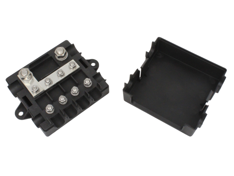
I really like that 3 postition mrbf fuse block but if you want 4 positions...
or this
 
Love the Mega & Midi thing but I cannot find a voltage spec for them.

Since the website has 12v in the name should I assume these are not spec’d for 48v use?
 
Why not stay 24v and use buck converters for 12v switched and unswitched loads?
 
Love the Mega & Midi thing but I cannot find a voltage spec for them.

Since the website has 12v in the name should I assume these are not spec’d for 48v use?

I think they are both rated to 32 volts only.
 
Why not stay 24v and use buck converters for 12v switched and unswitched loads?

I was going to suggest that it would simplify things big time to run 12 volts.
for 400 amps aggregate load its a pita but doable.
 
Last edited:
It took me a while to find where I saw this but see here for a couple that did six 48 to 12v buck converters to run their bus 12v needs:

 
Back
Top