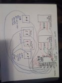
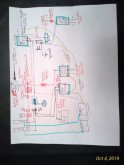
Are there any problems associated with connecting/disconnecting via relay the batteries from the MPPT SCCs?
So I suppose there are two questions embedded in this question:
First, is it safe for the battery protect to be used in this manner?
As far as I know, this is as acceptable but non-conventional way to use the battery protect
(see this thread) more specifically
@Justin Laureltec's
response. But its something I would confirm with Victron before moving forward if I stick with this design.
Second, is it safe for the charge controllers to be disconnected from the battery while connected to the PV panels?
Conventional wisdom not so long ago was that this was not a good idea. However, this perception seems to be shifting (see Will's thread
"Trying to destroy my SCC's, I can't") Victron's documentation doesn't caution against this or otherwise indicate that this is a bad idea or would void their warranty. See
post #42 and #43 for more info and a good explanation from Justin, that pretty much puts the issue to rest in my eyes, at least with Victron controllers.
Why use several MPPT SCCs
This is a practice seen mostly in the marine world where rigging, sails, etc can really screw with solar output. I'm incorporating it as part of my strategy to mitigate partial and unpredictable shading. 1:1 panel to MPPT ratio means partial shade on 1 panel has no effect on the others, and each controller can determine the maximum power point specific to the panel hooked up to it. I understand the theoretical benefits of this, I have no idea what the real world gains will be, and haven't been able to find much data on it, but its often recommended in the marine world and the difference in price between 3 small controllers or 1 larger controller is pretty negligible ($355 for 3x 75v/15a, or $325 for 1 x 100v/50a) so I'm willing to pay a little more for the theoretical benefits.
Its part of my broader attempt to mitigate partial shade
- Use panels designed to perform better in partial shade (like REC Peak or Alpha panels or Sunpower X series or P series)
- Use higher voltage panels and minimize or eliminate series connections
- Multiple MPPT controllers
- Possibly make one of the 3 solar 'modules' portable so if I'm camped in the shade I can set up one module in the sun away from the vehicle. Probable won't end up doing this, but its an option.
If you, or anyone else is interested, I have started several threads
(see here) on partial shade performance, as questions have come up and as I've learned.
As I mentioned, this is a super early working draft of the system I'm designing, so a lot will probably change, and I very much welcome questions, criticism, tire kicking, recommendations, and second guessing
")


.png")
.png")
