


You are using an out of date browser. It may not display this or other websites correctly.
You should upgrade or use an alternative browser.
You should upgrade or use an alternative browser.
BYD 24 volt 5k used liFePO4 order
- Thread starter michael d
- Start date
GVSolar
Solar Enthusiast
- Joined
- Jan 6, 2020
- Messages
- 455
As you know, there’s been a great deal of discussion about the actual useful capacity of these used BYD 24v batteries. Perhaps this post will be informative. Please forgive the lousy formatting - I took my notes in a word processor, not a spreadsheet.
Here are the basic breakdowns of the charge/recharge cycles that I used to “wake up” my Tech Direct/BYD units. I repeated the same charge/discharge cycle three times with varying depths of discharge.
First I charged each unit separately to an equal voltage of 26.3. Then I individually charged all three units with an 800w LFP Charger (23 amp average charge) - to an equal voltage of 28v (that’s the BMS cutoff). I then connected all three units in parallel - and discharged them all to 24 volts using a 500 watt heater. I then recharged them again to 28volts.
Round ONE Charge to 28v
(A/B/C Combo) Lifepo4 Charger Profile 800w LFP Charger17.2 hoursR1
(Battery B’s meter shows .1 less voltage than reading taken at terminals)
TIME CHARGE Current CHmeter BATT A BATT B+.1 BATT C
1/24/20 DC bulk 23a/b/c 26.7 28.0 27.9 28.0
First Discharge to 24v:
Round One Discharge (A/B/C Combo) to 24v
TIME DISCHARGE Current METER BATT A BATT B+.1 BATT
1/29/20 END 18.1 amps 24.0 24.0 23.8 23.9
TIME Capacity Energy METER Time Int R Ext R
2:09 END 315 AH 8.14 kwh 24.0 17:12 hrs 216 mOhms 1.4 Ohms
Recharge again to 28V (BMS cutoff):
Round TWO Re-Charge to 28V
(A/B/C Combo) Lifepo4 Re-CHARGE Profile 800w LFP Charger14:35 hours R2
TIME CHARGE Current CHmeter BATT A BATT B+.1 BATT C
1:35 pm DC 621w 23a/b/c 27.2 27.5 28*cutoff 27.5
(A/B/C Combo) Lifepo4 METER PROFILEwith LFP Charger ReCharge #2 to 28v
TIME Capacity Energy Meter Time Int R Ext R
1/31/20 @ rest for .5 hour
2:30pm start 0 wh 23.8 0 min 155mOhms 1.1Ohms
1:35pm 326 AH 8.68 Kwh 27.5 14:35 hr 0 mOhms 1.2 Ohm*
My second discharge was to 23.5 volts:
Round Two DISCHARGE TEST to 23.5v – three hours rest
(A/B/C Combo) Lifepo4 METER PROFILE500w approximate discharge
TIME Capacity Energy METER Time Int R Ext R
2/3/20 reset AH reset wh 2.2 0 min
4:30pm 0 AH 0 wh 26.7 start 68 mOhms 1.4 Ohms
1:54 END 319 AH 8.23 kwh 23.5 17:14 hrs 246 mOhms 1.3 Ohms
(A/B/C Combo) Lifepo4 DISCHARGE Profile#2with Inverter & Heater (Bmeter)
TIME DISCHARGE Current METER BATT A BATT B+.1 BATTC
2/3/20 @ rest - 3 hrs (small) 26.7 26.6 (7) 26.7
1:54 END 17:14 hrs 18.1 amps 23.5 23.4 23.4-3 23.4
Recharge again to 28V (BMS cutoff):
Round THREE Re-Charge to 28V
(A/B/C Combo) Lifepo4 ReCharge Profile800w LFP ChargerR3
TIME CHARGE Current CHmeter% BATT A BATT B+.1 BATT C
2/5/20 @ rest for .5 hr 23.6 23.6 (7) 26.7
14.52 min 622 watts 27.8 28* 28*cutoff 28*OVER
TIME Capacity Energy Meter Time Int R Ext R
2/5/20 @ rest 1/2 hr (meter on) 178 mOhms 1.1 Ohms
1:52pm 333 AH 8.85 Kwh 27.8 14:52 hr 0 mOhms 1.2 Ohm*
My third Discharge was to 23 volts:
(A/B/C Combo) Lifepo4 DISCHARGE Profile#3with Inverter & Heater (Bmeter)
TIME DISCHARGE Current METER BATT A BATT B+.1 BATTC
2/8/20 @ rest 3 hrs (small) 26.7 26.6 (7) 26.7
6:00pm start 500w nom 26.7 26.6 26.5 26.6
11:55 END 17:55 hrs 420 watts 23.2 23.2/1 23.0 23.1
DISCHARGE TEST – Round THREE 3 hours rest
(A/B/C Combo) Lifepo4 METER PROFILE500w discharge
TIME Capacity Energy METER Time Int R Ext R
2/8/20 reset AH reset wh 26.8 0 min
6:00pm 0 AH 0 wh 26.8 start 71 mOhms 1.4 Ohms
11:55 END 322 AH 8.32 kwh 23.2 17:55 hrs 263 mOhms 1.3 Ohms
After the next 28v recharge I’ll prepare the batteries for service in my main system. My home is completely off-grid (30+ years) - looking forward to finding out how these batteries perform in a real world situation.
Some very general observations:
As you can see, the recorded battery capacity rose in each charge/discharge cycle – obviously because of the constantly increasing depth of discharge/recharge. Whether that will represent a general increase in capacity over time remains to be seen.
As an approximate average, I would rate the usable capacity of these three TD/BYDs at 110AH/2.95kwh each, or 330AH/8.85kwh total.
Not bad for a 4-6 year old battery of unknown heritage... and for the money, an excellent bargain (assuming at least another 5 years of good service). A comparable Battleborn battery bank would have been triple the cost. For the AES/Discover Batteries – five times the cost. Of course, then I would have the peace of mind given by a 10 year warranty (but not nearly the same learning curve/fun). And I genuinely prefer the form factor of these refurbished units – especially their well-built roll-a-round cases.
How the TD built-in BMS will perform over time remains to be seen. Because the TechDirect BMS has no cell level monitoring I elected not to push my discharge tests any lower than 23.0v. Only time will tell how the batteries respond to the constant usage (and varying charge/discharge rates) of off-grid living, but overall I am satisfied with the current usable capacity of these TechDirect units.
Some people have reported higher total AH/Kwh; I suspect that is the result of active balancing at cell level with an outboard BMS - and possibly an earlier generation of BYDs that were capacity tested before sale.
One other note: As expected, a charge from 27 to 28 volts took less than 30 minutes – and the last half-volt happened in less than 5 minutes. That sudden uptick/dropoff would occur in discharge as well – something to be keenly aware of when I program my final solar charging parameters.
If you have a meter setup that allows for it, the battery’s internal resistance seems to be an excellent indicator of actual SOC. During my charge cycle IR would end at damn near zero and begin at something close to 180 mOhms. The reverse is true for the discharge cycle – ending IR was at about 263 mOhms at 23v. In the midzone (where there is very little voltage shift) keeping an eye on that internal resistance reading could be very helpful in determining true SOC.
As always, your mileage may vary downhill in a tailwind. Hope some of this was helpful, and best to all.
GV,
Curious as to what you ended up using for the charge limit on your charge controller. Was it 28v? I have mine set for 28.4, but right around there the internal BMS cuts out. The ammeter shows 28.5, but it's pretty cheap, and with the LA bank in parallel, it's probably not 100% accurate.
My goal is for the internal BMS to not disconnect the load. I have an older lead acid bank in parallel, so when the lithium bank disconnects, the charge controller still functions off that bank, but I hate having to trust the internal BMS to kill power to the battery.
Attachments
GVSolar
Solar Enthusiast
- Joined
- Jan 6, 2020
- Messages
- 455
Once my installation is complete I will be using 27.2v as a charge controller starting point. Like you, I don't think it is wise to use the internal BMS cutoff - especially if (like me) the batteries are connected in parallel (one BMS shuts off and then the current rises on the other two - and then they all suddenly shut off). For me, better to adjust the top end to a lower voltage, at just the beginning of the upper slope - I will observe that effect - and then vary that voltage up or down according to the results. My feeling is not to push these BYDs too hard - they are already compromised by age and possibly by overcharge/discharge. Let me know how they are working for you. Good luck and best to you.
Once my installation is complete I will be using 27.2v as a charge controller starting point. Like you, I don't think it is wise to use the internal BMS cutoff - especially if (like me) the batteries are connected in parallel (one BMS shuts off and then the current rises on the other two - and then they all suddenly shut off). For me, better to adjust the top end to a lower voltage, at just the beginning of the upper slope - I will observe that effect - and then vary that voltage up or down according to the results. My feeling is not to push these BYDs too hard - they are already compromised by age and possibly by overcharge/discharge. Let me know how they are working for you. Good luck and best to you.
GV,
Oh wow, at 28.4, I have it set way too high. I'll give that a try as well. I did notice from watching the voltage rise while charging, that right around 27.2 to 27.4, the voltage did start to rise quite quickly. I have a USB ameter coming from china (https://www.ebay.com/itm/PEACEFAIR-...rgy-Consumption-Meter-Module-New/223455997983). Once it's in, I'm hoping to really map out the charging pattern.
your running LA batts with lithium together in parallel?GV,
Curious as to what you ended up using for the charge limit on your charge controller. Was it 28v? I have mine set for 28.4, but right around there the internal BMS cuts out. The ammeter shows 28.5, but it's pretty cheap, and with the LA bank in parallel, it's probably not 100% accurate.
My goal is for the internal BMS to not disconnect the load. I have an older lead acid bank in parallel, so when the lithium bank disconnects, the charge controller still functions off that bank, but I hate having to trust the internal BMS to kill power to the battery.
GVSolar
Solar Enthusiast
- Joined
- Jan 6, 2020
- Messages
- 455
StevieP - Probably a good idea to run an A/B switch and top off the LA bank from time to time... if you haven't done so already. Set the CC's for LFP - they'll take a lot more damage from a LA charging profile than LA will from an LFP charging regimen.
your running LA batts with lithium together in parallel?
Yes I run them in parallel but I have the charge controller set for led acid, and turn off the led acid and lithium banks at certain voltages using relays. The lead acid bank mostly stays topped off. I only dip into it when nesisary after the lithium back gets down to 24v, or is full. I then let the led acid bank sit connected at float until the sun goes down. I use a raspberry pi connected to a really board to automate it.
StevieP - Probably a good idea to run an A/B switch and top off the LA bank from time to time... if you haven't done so already. Set the CC's for LFP - they'll take a lot more damage from a LA charging profile than LA will from an LFP charging regimen.
GV,
I also disconnect the lead acid bank every month or so and charge them to full from a battery charger.
I also set the charge controller to not equalize, and have the charge limit turned down slightly to 28.4 for the reasons you lost above.
Clever fellow, that Steviep19...
GV,
I tried lowering the charge limit like you have done, and the lithium BMS is no longer disconnecting. Thanks for the advise.
GVSolar
Solar Enthusiast
- Joined
- Jan 6, 2020
- Messages
- 455
Glad to be of service. The individual cells in those BYDs are likely a bit out of whack... I'm going to try to stay below the disconnect for balancing, and well below that for day to day usage. Too bad the BMS doesn't have any way to monitor cell voltage... I wish someone would come up with a way to interface with those TD/BMSs....
MountainMatt
M&M Overland Adventures
Hey GV,Did my first charge/discharge cycle with 3 paralleled pre-assembled TechDirect/BYD units: They were fully charged to the internal BMS cutoff of 28v. Using a 500w heater @ approx 18amp discharge the batteries lasted for 17 hours 12 minutes - using a cut-off voltage of 24.0v.
Didn't want to press the voltage any lower on my first discharge cycle. At 24.v my meter read: 8.14Kwh, 315Ah.
That would represent 2.71kwh/105ah per battery. It's not 4Kwh per battery, but it's a start, and there may be some operator error in there.
I've started the recharge cycle and will be more rigorous in my measurements next time - we'll see if the capacity increases with each "wake up" cycle. I will also push the discharge voltage a little more aggressively - perhaps as low as 23volts. Best to all.
What kind of meter are you using to give these details? Shunts, connectors etc.. with pics and links for the ignorant like me would be nice.?
Last edited:
MountainMatt
M&M Overland Adventures
Finally found this, THANKS GV!
8S LFP LifoPo4 BMS Detail Min Standard Max Single cell overcharge protection voltage 3.72 V 3.75 V 3.78 V Single cell overcharge protection delay time 0.6S 1.0S 1.5S Single cell overcharge recovery voltage 3.50 A 3.60 A 3.60 A Recharge current / / 130A Single-section equalization voltage 3.55 V 3.60 V 3.65 V Single-section equalization current 35 mA 40 mA 45 mA Single cell over-discharge protection voltage 2.15 V 2.70 V 2.80 V Single cell over-discharge protection delay time 0.6S 1.0S 1.5S Single cell over-discharge release voltage / / 130A Discharge protection current 350 A 370 A 390 A Charging high temperature protection 85'C 90'C 95'C
FYI: These are the TechDirect specs listed for the built-in BMS unit.
GVSolar
Solar Enthusiast
- Joined
- Jan 6, 2020
- Messages
- 455
Hi Matt,Hey GV,
What kind of meter are you using to give these details? Shunts, connectors etc.. with pics and links for the ignorant like me would be nice.?
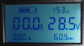
I've posted this picture before - it's how I took my original measurements. A cheap eBay 200a ammeter w/shunt -

DC 0-200V Solar Power Multimeter Ammeter Voltmeter Battery Tester Monitor T6U4 | eBay
Type 3: Tester + 100A shunt. Type 4: Tester + 200A shunt. Type 5: Tester + 300A shunt. 1 Battery Tester Monitor. Internal Resistance Minimum resolution: 1mΩ. 9 datas shown in the one screen, allows you catch the information you want at a glance.
www.ebay.com
Nothing tricky - you just have to make sure not to overcharge or over-discharge. My measurements were from 23.5v (low) to 27.5 high (BMS disconnects right around 28v).
In my actual working installation I am using Schneider Conext charge controllers and inverter - and they have built in monitoring which goes by xanbus to my Mac or my iPad. Best of luck...
Attachments
MountainMatt
M&M Overland Adventures
Thanks GV!Hi Matt,
I've posted this picture before - it's how I took my original measurements. A cheap eBay 200a ammeter w/shunt -
attached to two 3/8" battery posts (carefully separated). I bought the custom TechDirect anderson SB75 connectors with 3/8" lugs to connect - and alternated between 23amp battery charger (for recharge measurements) and a cheap 24v inverter/500w heater (for discharge measurements). There are detailed instructions for that meter (and others) if you search by model number or eBay listing.DC 0-200V Solar Power Multimeter Ammeter Voltmeter Battery Tester Monitor T6U4 | eBay
Type 3: Tester + 100A shunt. Type 4: Tester + 200A shunt. Type 5: Tester + 300A shunt. 1 Battery Tester Monitor. Internal Resistance Minimum resolution: 1mΩ. 9 datas shown in the one screen, allows you catch the information you want at a glance.www.ebay.com
Nothing tricky - you just have to make sure not to overcharge or over-discharge. My measurements were from 23.5v (low) to 27.5 high (BMS disconnects right around 28v).
In my actual working installation I am using Schneider Conext charge controllers and inverter - and they have built in monitoring which goes by xanbus to my Mac or my iPad. Best of luck...
Nice setup, you got 3 of them bad boys!
I have a Schneider XW4024 inverter and am using the
| I have a Schneider XW4024 inverter and am using the Schneider, System Control Panel, for Conext XW... for battery charging from the grid to my 3-parallel wired 24v BYD power walls. Can you show a close up of your wiring? Does the context scp work well with the BYD? I still need Anderson connectors. How do you get the positive and negative post to opposite ends of the battery? |
GVSolar
Solar Enthusiast
- Joined
- Jan 6, 2020
- Messages
- 455
Hi totalicf:
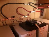
You can get Anderson connectors with #6 wiring (for both parallel and series) made at TechDirectClub - with custom lugs. I did so. Or try BatteryCablesUSA for larger wire sizes. I have 4 BYD pre-built units so my net charge/discharge amperage per unit is appropriate for a #6 cable.
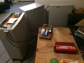
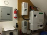
As to wiring: I used negative and positive busbars (see photos) and 200 amp type T fuses. I wired my SW4024 using Schneider switchgear components - my battery room is located directly behind the wall of that Conext installation. The unit lying on top of the batteries is a temporary test bed for a Moe's automatic transfer switch.
The Conext SCP works very well - but it is designed to be used with the SW4024 inverter (and any Conext charge controllers or AGS). It does not interface directly with the BYD units - it simply sees them as a "battery" - reporting their relative voltage and amperage in/out. However, if you integrate a Conext Combox with your system you can access robust system realtime monitoring & graphs and easily set system parameters for your Conext charge controllers and inverter (via iPad or phone as well). This really helps to keep on top of the day to day management of the system.
There is a sticky thread for Wiring Unlimited on the forum should you want to consult any wiring diagrams.
Best of luck and good thoughts.
You can get Anderson connectors with #6 wiring (for both parallel and series) made at TechDirectClub - with custom lugs. I did so. Or try BatteryCablesUSA for larger wire sizes. I have 4 BYD pre-built units so my net charge/discharge amperage per unit is appropriate for a #6 cable.
As to wiring: I used negative and positive busbars (see photos) and 200 amp type T fuses. I wired my SW4024 using Schneider switchgear components - my battery room is located directly behind the wall of that Conext installation. The unit lying on top of the batteries is a temporary test bed for a Moe's automatic transfer switch.
The Conext SCP works very well - but it is designed to be used with the SW4024 inverter (and any Conext charge controllers or AGS). It does not interface directly with the BYD units - it simply sees them as a "battery" - reporting their relative voltage and amperage in/out. However, if you integrate a Conext Combox with your system you can access robust system realtime monitoring & graphs and easily set system parameters for your Conext charge controllers and inverter (via iPad or phone as well). This really helps to keep on top of the day to day management of the system.
There is a sticky thread for Wiring Unlimited on the forum should you want to consult any wiring diagrams.
Best of luck and good thoughts.
Attachments
MountainMatt
M&M Overland Adventures
Very nice job GV!Hi totalicf:
You can get Anderson connectors with #6 wiring (for both parallel and series) made at TechDirectClub - with custom lugs. I did so. Or try BatteryCablesUSA for larger wire sizes. I have 4 BYD pre-built units so my net charge/discharge amperage per unit is appropriate for a #6 cable.
As to wiring: I used negative and positive busbars (see photos) and 200 amp type T fuses. I wired my SW4024 using Schneider switchgear components - my battery room is located directly behind the wall of that Conext installation. The unit lying on top of the batteries is a temporary test bed for a Moe's automatic transfer switch.
The Conext SCP works very well - but it is designed to be used with the SW4024 inverter (and any Conext charge controllers or AGS). It does not interface directly with the BYD units - it simply sees them as a "battery" - reporting their relative voltage and amperage in/out. However, if you integrate a Conext Combox with your system you can access robust system realtime monitoring & graphs and easily set system parameters for your Conext charge controllers and inverter (via iPad or phone as well). This really helps to keep on top of the day to day management of the system.
There is a sticky thread for Wiring Unlimited on the forum should you want to consult any wiring diagrams.
Best of luck and good thoughts.
Similar threads
- Replies
- 3
- Views
- 226
- Replies
- 18
- Views
- 1K
- Replies
- 5
- Views
- 428