diy solar

diy solar

Seplos CAN BUS RS485 48v 200A 8S-16S BMS

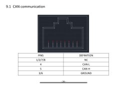
Righty guys, getting nowhere fast. Back onto comms lead making. Looking at the resources, Seplos use
CAN-L on pin 4
CAN-H on pin 5
GROUND 3/6

RS485-B on pin 1/8
RS485-A on pin 2/7
GROUND 3

Soooo, my LuxPower tek3600ACS has a RS485/CAN port, do i make a lead using both or just stick to one form of communication and if so, which is best, CAN or RS485?
Also, where it states 2 numbers on a pin ie 1/8, do i have to connect into both or just choose 1 pin?
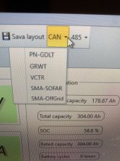
I have the latest 200A BMS which i think supports both formats.
Last but not least, if i am required to make a dual comms lead, which plug would i put it into on the BMS?
 
RS485 is slighly better than CAN, because it sends some more data (eg for multipack battery), but I would not worry.
I am actually thinking of disconnecting the bms from the inverter. This way, if I correctly set the stauration voltage on the inverter, I get a nice charging curve. With the bms controling the charge, on command, the inverter drops the current from 140A to 10A, while with the inverter setting the satuaraion voltage the current drops gradually. So potentially BMS will not allow to push as much charge into the battery in a limited time if I needed (I dont). And it's not like the MBS does not want to. The Pylontech protocol does not have the command "stay on this voltage", which would be useful, it only has a command for setting "Charge Current Limit".
 
Steve, if your LuxPower connects to the battery by CAN (probably the case) then you just need the CAN connections.

IMPORTANT
The latest SEPLOS manual for the 200A BMS is wrong, and the CAN L and H lines are swapped. I have informed SEPLOS about it but they are refusing to acknowledge that it's wrong!

The picture attached from the manual shows the WRONG information. In reality pin 4 is CANH and pin 5 is CANL.

The manual for the 100A BMS is correct.

Good luck!
 

Attachments

  • A094FF18-608A-44A7-A27D-2279892F0754.jpeg
    A094FF18-608A-44A7-A27D-2279892F0754.jpeg
    300.4 KB · Views: 25
Thank you both. I’ll probably try both individually and see how I go. Another problem ( ? ) I may have stumbled across is according to the LuxPower user manual, the LuxPower doesn’t use a ground in its pin out. Do you think this is correct?
 
Thank you both. I’ll probably try both individually and see how I go. Another problem ( ? ) I may have stumbled across is according to the LuxPower user manual, the LuxPower doesn’t use a ground in its pin out. Do you think this is correct?
CANBus (as implemented by SEPLOS) needs a ground connection.
 
Well, i tried and failed again. Made a CAN lead up and its still the same. I can only get a 'no fault' status on my inverter when i'm running as a lead acid battery. In fact, everything seems to run ok in this setting but i'm aware it isn't right. Also, in the Seplos battery monitor software, there is no option for Pylon which is what i think i'm supposed to be set to.
My dreams of a simple plug & play battery system are turning into a bit of a nightmare!!
 
Pylontech is probaly the default protocol for the bms, I did not need to set it. Did you make the cable like in the post #79?
 
Not exactly as my CAN is on pins 3&4 for my inverter. Works fine when the inverter is set to lead acid; reads the volts and gives a SOC ( although it’s wrong ). As soon as I use the Li-on setting I get a comms error and no comms. Might try the RS485 instead.
 
Not exactly as my CAN is on pins 3&4 for my inverter. Works fine when the inverter is set to lead acid; reads the volts and gives a SOC ( although it’s wrong ). As soon as I use the Li-on setting I get a comms error and no comms. Might try the RS485 instead.
Steve, the reason that the Lead Acid setting seems to work is because it does not require any comms on CAN, so don't worry about that.

The issue you've got is that comms is not working.

Step 1 is to make sure the wiring connections are correct.

Step 2 is to make sure the comms protocol is correct.

Can you post the following information:

What model of inverter?
What wiring are you using on the CAN cable? Draw it for us with pin numbers.
Post a screenshot of your BMS software.

This is not a plug and play domain.
 
I’ve got a LuxPower 3600ACS AC coupled inverter. My latest lead uses, Seplos end:
Pin 4 - CAN L
Pin 5 - CAN H

Inverter end:
Pin 3 - CAN L
Pin 4 -CAN H

This is the latest 200A 16s unit I’m using.

You posted earlier about the wires needing reversing and I’ll do this tomorrow ( I use the works crimper ) and I’ll also make an RS485 cable too.
My BMS software is just the standard downloaded Seplos program. I can’t screenshot it at the mo as I have to drag my pc downstairs and connect it up as my laptop is too old to run it. I’ll do this tomorrow.
Thank you for your help with this.
Yep, your wiring is incorrect, so you need to fix that.
I will have a look at the inverter regarding the lack of ground connection, as that could still be a problem for the wiring.

The reason I asked for the screenshot was to investigate what protocol/configuration you have running.
 
Well I’ve changed the wiring around, tried it on the 485 too and nothing works. Useless piece of chinese rubbish!! May as well leave it on lead acid as it functions fairly well on that.
Thanks for trying.
 
Last edited:
Mine started communicating with the inverter on the first try. CAN communication to an SMA Sunny Boy. The Seplos folks have numbered the RJ45 pins in reverse order in the manual. This does not impact the RJ485 as the pinout are symmetrical.

And for CAN communication you need 3 wires - CAN L, CAN H, and ground. From what I've read it goes the same for RJ485.

It is a long thread (and I'm not going through it) but did you:
1) Set the correct CAN protocol in the Battery Monitor software?
2) Wire the cable correctly? If you know your inverter pinout (I found it out on the previous page) and provide a picture of the cable that you use (with visible cables from the bottom side of the connector) I can verify it is correctly wired.
 
I’ll try and get some pics of the wiring tomorrow ( had a gut full of it today ).
The protocol has no setting for LuxPower or Pylontech in my software. It’s been mentioned previously that it defaults to Pylontech but I have no idea on this. The LuxPower pin out drawing shows no ground.
 
I did a bit more searching on this. Common ground is not required but is recommended. You may end up with a damaged inverter or BMS without it. It depends on how the hardware implementation and if it is galvanically isolated. I'll have to check the spare BMS I have to see if it is galvanically isolated, but from what I've found while I was looking at the PCB it doesn't look to be.

Ignoring that fact - CAN uses the two wires for differential signals. If CAN_H to CAN_L voltage difference is above a certain threshold voltage it is 1, if it is below another threshold voltage - it is 0. So in theory it can work without ground.

The same goes for the RS485. It uses the differential voltage between A and B to determine if it is 1 or 0, but in another manner - it is either A > B or B > A. The voltage difference again needs to be above a certain threshold.


Looking at the "Luxpower Compatible Battery List" - the first entry is "Pylon". I suppose this is the Pylontech protocol. And it states CAN support only, not RS485 for it.

Your wiring when looking on the bottom side of the RJ45 connector at the cable should be as follows:
LuxPower: NC - NC - CAN_L - CAN_H - NC - NC - NC - GND
Seplos: NC - NC - GND - CAN_H - CAN_L - GND - NC - NC

3 wires:
1) LuxPower 3 to Seplos 5
2) LuxPower 4 to Seplos 4
3) LuxPower 8 to Seplos 3 or 6 (one of them is sufficient)

And once you power up your inverter you need to go through the LCD to set up the battery type as Pylontech.
 
Last edited:
I’ll try and get some pics of the wiring tomorrow ( had a gut full of it today ).
The protocol has no setting for LuxPower or Pylontech in my software. It’s been mentioned previously that it defaults to Pylontech but I have no idea on this. The LuxPower pin out drawing shows no ground.
Steve,
Don't forget you need to log in to the BMS software to select the protocol.
Then you can set it at the top RHS of the screen.
 
Mariner62, if you mean the admin/admin login, I’ve already tried that and neither Pylontech or LuxPower are on the drop down.
 
Brum
I’m gonna start from scratch with a new, tested lead but your wiring explanation is what I have already tried. Picked up one of those reusable rj plugs so should be a lot easier.
 
If your wiring is correct then the only missing part is the software settings. Both the BMS and the inverter should be configured to the Pylontech protocol. I don't recall how mine Seplos was looking, but I just choose the SMA entry in the list and it worked as a charm.

Looking at google videos once you click the "CAN" dropdown there should be "Pylon" as the first option, Growatt as the second option, and the list goes by. If you don't see "Pylon" on the top of the list take a screenshot (or picture with the phone) so we can see what options you have there.
 
Righty. Finally got comms. Turned out my first new lead was faulty ( no continuity on the blue wire ) so that’ll teach me to check my leads even if they’re new. Think everything is running ok now and guessing the software is defaulted to Pylontech as it’s not in the drop down
What can I actually do with this Seplos software or is it more a monitoring/ fault finding thing?
 

Attachments

  • 5C2470BB-955A-4A2E-9BD9-E2689BF7D194.jpeg
    5C2470BB-955A-4A2E-9BD9-E2689BF7D194.jpeg
    221.6 KB · Views: 23
  • image.jpg
    image.jpg
    119.5 KB · Views: 23
Hi all. Can anyone recommend the best settings for 280ah, 200A BMS. My cells stop discharging at 24% at the moment. I'm getting the Monomer Low Pressure Alarm. Any ideas?
 

diy solar

diy solar
Back
Top