diy solar

diy solar

EVE LF280K cells testing positive between negative pole and the blue body

Or you could just check for continuity between the cell casings, with your multimeter. By placing the leads on the QR code of the cells beside each other.
 
This is what I suspect that seems to make sense to me. The casings of the cells are shorted and when you move them it just makes it worse. I suspect that some of the copper shavings got between the cells and is breaking through the thin plastic insulation. When the cells are compressed then the thin copper shavings are just shorting out your casings and then when you connect the bus bar then sparks start to fly. This can easily be verified with a voltmeter. To remedy the issue then as others have suggested, remove the copper debris and place an insulation material between the cells. Also remove all of the copper shavings from the bottom of the cells as well.
 
Looks like you are installing the bus bars in series correctly.

With all the bus bars off measure voltage from one cell to the next. Try lots of combinations of terminals and cell casings from one battery to about. In no situation should you see any voltage. If you do there's a connection between the cases that your FR4 insulation missed.
 
And definitely inspect under the cells to make sure you aren't shorting on the threaded rods below. If you have more PC board, consider using a layer under the cells also.

I would not use Plastidip for this job, by the way. A more durable and reliable way to cover the threaded rods is with plastic pipe such as PEX or PVC.
 
All's well that ends well. I didn't find traces of copper. I covered the QR Code next to the blue "window" area with Kapton tape to insulate the cell casing from any stray electricity and patched a few dings with rubber cement and Kapton tape. Covered the bottom of a couple of cells with Kapton tape. I checked the threaded bars/ screws for any touching and made sure the four cells in the compression assembly were flat/ even. That seemed to fix the sparking.

Now, I'm assembling the OverKill 100 amp, 8s, 24 volt BMS and I'm not sure what gage of wire to use for plus and minus (B- and C-). I'm using one BMS per 8 EVE LF280K cells and both bank will be connected to the same bus bars. The company gave me these directions:
"If you are having a cable come from both M6 terminal blocks I would recommend 4awg wire. If you are putting a
bus bar across the two terminals I would go with a 2/0 AWG wire." I'm not sure what that means exactly. I have plenty of 1/0 AWG wire from the last project.
 

Attachments

  • Overkill BMS (1).png
    Overkill BMS (1).png
    377.8 KB · Views: 8
What I think is going to happen is this: Below is a picture of the terminals to connect the bus bar to. Then yes tap a screw hole and secure a 2/0 wire from there. Not real sure how many bus bars attach to the BMS in the circled terminals or how many 2/0 wires are attached to the bus bars. Is it one wire per bus bar? Can the screw hole be skipped and the 2/0 AWG wire connect to one of the terminal screws?
 

Attachments

  • BMS Terminal.png
    BMS Terminal.png
    188.9 KB · Views: 14
Can the screw hole be skipped and the 2/0 AWG wire connect to one of the terminal screws?
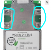
To be clear, the flat part of the cable lug should be fastened by the screw to the BMS port. Overkill has a fairly extensive instruction set. For more surface area two or three positions are available for attaching multiple smaller wires all going to the same battery terminal or bus bar, as seen in the picture you posted above.
 
Last edited:
I think I will have to email them unless someone has a telephone number. I don't see the gauge or the positioning of the wires on this BMS. I should have ordered it with the wires. I didn't think it would be this complicated. They did not explain much and added more confusion than anything. The impression from their email is that a bus bar can be joined to the two terminals on both B- and C-.
 
Yea, I combined it with under 2 minutes of searching the model number on duckduckgo...
These should get you going.


Edit - can't keep track of who I'm replying to but the above should still help others.
 
Yes it does. How do you get the wires to the battery? What I see is two bus bars over B- and C- but I don't see the black wires and the blue wires going to the battery or the load. So, I guess I don't get it. Sorry, I'm dense.
 
Last edited:
How do you get the wires to the battery? What I see is two bus bars over B- and C- but I don't see the black wires and the blue wires going to the battery or the load.
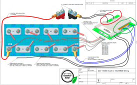
The last picture is a different BMS. If yours is the one in post#46 & 47 just follow the pictures.
 
Yes it does. How do you get the wires to the battery? What I see is two bus bars over B- and C- but I don't see the black wires and the blue wires going to the battery or the load. So, I guess I don't get it. Sorry, I'm dense.
Lug your big wires to the bus bars you install. Somewhere right in the middle would be great. Drill the proper size hole, pass a stainless bolt through from the bottom, and put your lug on and then a stainless washer and nut.

If your bolt won't fit between the existing lugs on the board, extend your bus bar and put your lug on the end.
 
Back
Top