WindWizard
Solar Enthusiast
Time to get a meter out and measure to see where it is shorting out. If you get sparks with just one bus bar then it has to be shorting somewhere.


I was drilling holes in copper bus bars and made a bit of a mess but I think I cleaned the shavings up. That was awhile back.I'm glad to hear you are adding insulation between the cells. Are the sheets the same size as the cells? Not undersized?
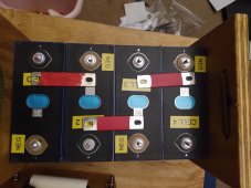
Can you draw out or demonstrate where you are adding bus bars?
Are the cells sitting on something conductive?
I wouldn't think so.I put some plasti-dip on the bus bars to insulate them. Could that be it?
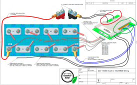
Where do you start and how to you find the short?Current has to flow from the negative terminal to the positive.
Can you show you bus bar lay out?
The Plasti-Dip did me in. I didn't see it. I'll clean up that mess before I try it again.One of the bus bars has goop on the contact and needs to be cleaned.
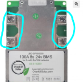
To be clear, the flat part of the cable lug should be fastened by the screw to the BMS port. Overkill has a fairly extensive instruction set. For more surface area two or three positions are available for attaching multiple smaller wires all going to the same battery terminal or bus bar, as seen in the picture you posted above.Can the screw hole be skipped and the 2/0 AWG wire connect to one of the terminal screws?