


You are using an out of date browser. It may not display this or other websites correctly.
You should upgrade or use an alternative browser.
You should upgrade or use an alternative browser.
JK BMS CAN bus comms now possible for inverters that support Goodwe and Pylontech batteries
- Thread starter uksa007
- Start date
uksa007
Solar Enthusiast
- Joined
- May 26, 2022
- Messages
- 239
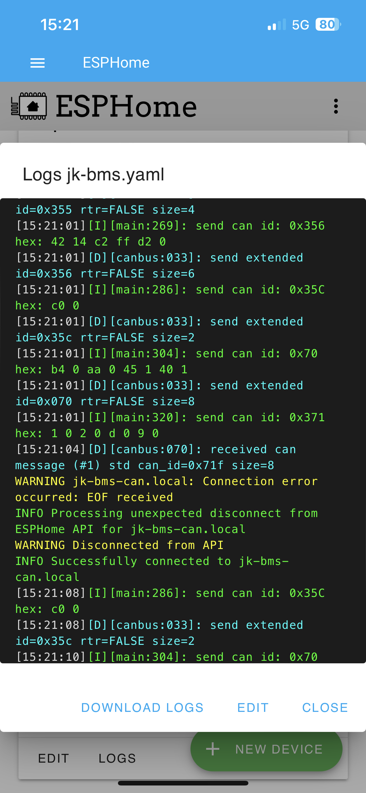
Any chance you can download the logs and attach them here?Here’s what I fetched
What is the value of "Uptime Human Readable" sensor in Home Assistant or in the logs?
It looks like the ESP disconnected from WiFi, what is its WiFi signal like?
Try to move it closer to the access point or try changing the channel on the access point
Last edited:
I have a repeater with the same ssid as the router and the esp has connected to the router instead of the repeater. I have specified the bssid instead the ssid and it works fineAny chance you can download the logs and attach them here?
What is the value of "Uptime Human Readable" sensor in Home Assistant or in the logs?
It looks like the ESP disconnected from WiFi, what is its WiFi signal like?
Try to move it closer to the access point or try changing the channel on the access point
")
Last edited:
uksa007
Solar Enthusiast
- Joined
- May 26, 2022
- Messages
- 239
What you have all been waiting for!
I have been working pretty hard on this for the last few months, it is very early Proof of Concept Multi BMS code.
Multi BMS Alpha code info
I have been working pretty hard on this for the last few months, it is very early Proof of Concept Multi BMS code.
Multi BMS Alpha code info
uksa007
Solar Enthusiast
- Joined
- May 26, 2022
- Messages
- 239
Multi BMS Alpha code now released.
Update: Alpha V2.16 more info here
I completed and implement the initial design, the data is now combined from the slaves as per the design.
I have made many improvements and made the code more robust, see the above link for more info.
Future plans include adding Multi BMS support for JBD/Overkill so you can mix and match BMS in the one larger pack.
thanks for doing this. What happens when one of the slaves or master stops accepting charge such as from a high cell voltage?Multi BMS Alpha code now released.
Update: Alpha V2.16 more info here
I completed and implement the initial design, the data is now combined from the slaves as per the design.
I have made many improvements and made the code more robust, see the above link for more info.
Future plans include adding Multi BMS support for JBD/Overkill so you can mix and match BMS in the one larger pack.
uksa007
Solar Enthusiast
- Joined
- May 26, 2022
- Messages
- 239
As per the design:thanks for doing this. What happens when one of the slaves or master stops accepting charge such as from a high cell voltage?
359 OR the Alarms (this may have some negative impacts but seems the safest option) IMPLEMENTED
Any BMS alarm for the master or slaves will be sent to the inverter.
Any alarm including slaves will set 0A for Discharge and Change and turn off all flags.
xristostsilis
New Member
- Joined
- Mar 24, 2022
- Messages
- 127
Hi! Thanks for all the great work! Do you have plans to support RS485 pylontech protocol with JK BMS for supported inverters in the future?
uksa007
Solar Enthusiast
- Joined
- May 26, 2022
- Messages
- 239
It's on my radar but not something that has many requests or any Patreon supporters, so I haven't progressed with it.Hi! Thanks for all the great work! Do you have plans to support RS485 pylontech protocol with JK BMS for supported inverters in the future?
xristostsilis
New Member
- Joined
- Mar 24, 2022
- Messages
- 127
Thanks for the reply. I really hope one day you will be able to make/release it as all of the voltronic inverters don’t support pylontech over CAN.It's on my radar but not something that has many requests or any Patreon supporters, so I haven't progressed with it.
Some support by the community would really help this project come to life one day.
uksa007
Solar Enthusiast
- Joined
- May 26, 2022
- Messages
- 239
Unfortunately there is a small minority of inverters that don't support CAN, poor design by the manufacturer if you ask me, as most of the batteries on the market use CAN.Thanks for the reply. I really hope one day you will be able to make/release it as all of the voltronic inverters don’t support pylontech over CAN.
Some support by the community would really help this project come to life one day.
xristostsilis
New Member
- Joined
- Mar 24, 2022
- Messages
- 127
That’s true unfortunately for us having these kind of inverters. I am hoping to find a solution in the futureUnfortunately there is a small minority of inverters that don't support CAN, poor design by the manufacturer if you ask me, as most of the batteries on the market use CAN.
kalle solis
New Member
Hi and thanks for the great project you done.
A quick question. Can I set up a kvaser can dongle to send and emulate the inverters can msg to the esp32 to see if everything works and so it doesn reboot?
What are the canmsg that needs to be sent and how often?
A quick question. Can I set up a kvaser can dongle to send and emulate the inverters can msg to the esp32 to see if everything works and so it doesn reboot?
What are the canmsg that needs to be sent and how often?
uksa007
Solar Enthusiast
- Joined
- May 26, 2022
- Messages
- 239
Hi and thanks for the great project you done.
A quick question. Can I set up a kvaser can dongle to send and emulate the inverters can msg to the esp32 to see if everything works and so it doesn reboot?
What are the canmsg that needs to be sent and how often?
It works great, myself and many others have been using it for year, with many different inverters.
You would need to send a empty(all 0x00) standard CAN ID 0x305 every second.
uksa007
Solar Enthusiast
- Joined
- May 26, 2022
- Messages
- 239
Starting to put some thought into support for Pylon RS485 protocol, does anyone have their inverter connected via RS485 and can log and send me some data?
Have progressed with creating code that produces the responses as per the Protocol, let me know if you have a data from the inverter.
eg what the inverter is asking it should be something like one of these:
rx_fixed {0x7E,0x32,0x30,0x30,0x32,0x34,0x36,0x34,0x32,0x45,0x30,0x30,0x32,0x30,0x32,0x46,0x44,0x33,0x33,0x0D}
rx_fixed_FF {0x7E,0x32,0x30,0x30,0x32,0x34,0x36,0x34,0x32,0x45,0x30,0x30,0x32,0x46,0x46,0x46,0x44,0x30,0x39,0x0D}
Last edited:
drtywheels
New Member
- Joined
- May 24, 2022
- Messages
- 2
Hi, I like your project and had been meaning to provide some feedback for a while now on my use and experience.
Up until yesterday I had connected this up to my JK-B2A20S20P BMS and 2 Growatt SPF5000ES inverters. Inverter setting 5 to "LI" and setting 36 to "52".
I'm now using a slightly older JK-BMS as the former let all the smoke out in an impressive way I still don't understand.
If I manage to attach photo's they will show the carnage. It's interesting to note the failure point being around the GPS port which is used to connect to the ESP32. I used the correct JST plug but unnecessarily connected the +ve to my cable. It goes nowhere at the other end and should not be the cause but it's hard to tell.
I've had this connected for nearly 6 months now.
I don't know if this was caused by something I had control over or just a BMS fault. It looks like heat has melted the JST socket to the point the solder melted and the socket moved. I'm not sure if this is the cause or result.
Anyway something to be aware of and maybe keep a look out for heat around this part of the BMS. I've now taped one of my temperature probes to the back of the BMS to keep an eye on it.
I'm glad I built a fire resistant cabinet for my battery and BMS.
As far as this projects goes I did find that the ESP rebooting due to no CAN response from the inverter to be a pain initially. I understand the need for a watchdog arrangement but the growatt interter will kill all output very quickly if it doesn't get a CAN message.
I stupidly connected my TJA1050 to 3.3v and not 5v initially which resulted in intermittent CAN communication and lots of inverter output shutdowns but once figured out it has been quite reliable.
I also updated the config to 300sec instead of 30 and that seems to have helped for just being able to monitor the BMS via home assistant if I do not have the CAN communication enabled.
I've changed the inverter to use manual settings (setting 5 to "US2") and not "LI" (ie no CAN comms) a couple of times (I'm trying to balance a cell I replaced recently and setting the inverter to "LI" (CAN enabled) causes problems as 100% is not 100%) but with the cables still connected between the ESP32 and the inverter
CAN ports the ESP32 still seems to send messages to the inverter to stop charging when it sees 100% on the BMS.
I haven't actually logged this yet but keep finding that the inverter max charging current setting (setting 2) is being set to 0 when I had previously manually set it to 50 or 60A.
Probably no big deal as I should have the battery type set to "LI" not "US2" but as my BMS capacity is inaccurate at the moment I need the inverter to just charge based on voltage not % so I have to unplug the CAN RJ45 cables.
Anyway great project. you saved me a lot of time trying to develop something similar myself.
Hello, I have an inverter with pylon rs485 protocol, and I would like to test it.Starting to put some thought into support for Pylon RS485 protocol, does anyone have their inverter connected via RS485 and can log and send me some data?
Have progressed with creating code that produces the responses as per the Protocol, let me know if you have a data from the inverter.
eg what the inverter is asking it should be something like one of these:
rx_fixed {0x7E,0x32,0x30,0x30,0x32,0x34,0x36,0x34,0x32,0x45,0x30,0x30,0x32,0x30,0x32,0x46,0x44,0x33,0x33,0x0D}
rx_fixed_FF {0x7E,0x32,0x30,0x30,0x32,0x34,0x36,0x34,0x32,0x45,0x30,0x30,0x32,0x46,0x46,0x46,0x44,0x30,0x39,0x0D}
I can log inverter requests, so I can send you next days
uksa007
Solar Enthusiast
- Joined
- May 26, 2022
- Messages
- 239
We are doing some testing over at https://github.com/Uksa007/esphome-jk-bms-can/discussions/27Hello, I have an inverter with pylon rs485 protocol, and I would like to test it.
I can log inverter requests, so I can send you next days
You are welcome to come and join the fun.
This is meWe are doing some testing over at https://github.com/Uksa007/esphome-jk-bms-can/discussions/27
You are welcome to come and join the fun.
guardianstar
New Member
Hi,
Can I connect BMS via BLE and make CAN BUS connect to inverter, because I cant open case to connect UART
Can I connect BMS via BLE and make CAN BUS connect to inverter, because I cant open case to connect UART
uksa007
Solar Enthusiast
- Joined
- May 26, 2022
- Messages
- 239
No, BLE is not supported.Hi,
Can I connect BMS via BLE and make CAN BUS connect to inverter, because I cant open case to connect UART
The connector is on the bottom of the JK-BMS, you don’t need to open the case.
My interface kit has all the needed hardware and cable for the BMS.
guardianstar
New Member
Thanks! I mean battery's case. Opening it will lost warrantyNo, BLE is not supported.
The connector is on the bottom of the JK-BMS, you don’t need to open the case.
My interface kit has all the needed hardware and cable for the BMS.
tonystrullu
New Member
Good morning
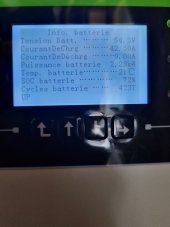
I am using the code from uksa007 on a SofarSolar HYD5000EP inverter and it works perfectly.
I just have a problem for the number of battery cycles. The value transmitted to the inverter corresponds to the current value.
What modification can I make to correct the information?
Thank you for your work it's great.
Attachments
Keith Moreau
New Member
- Joined
- Nov 18, 2019
- Messages
- 69
@uksa007
Hello, I just stumbled upon your project and I think it is fantastic. Will this work with 3 x Overkill (JBD) BMSs connected to 3 separate battery banks connected to a Sol-Ark 12K or a Sol-Ark 15K? Has anybody tested this multi-BMS configuration with Sol-Ark protocols? My banks are not identical, 2 are 16s 272 ah Lishen cells and 1 16s 280ah EVE bank. Currently all are working well on their own and paralleled to the Sol-Ark. Thanks much!
Hello, I just stumbled upon your project and I think it is fantastic. Will this work with 3 x Overkill (JBD) BMSs connected to 3 separate battery banks connected to a Sol-Ark 12K or a Sol-Ark 15K? Has anybody tested this multi-BMS configuration with Sol-Ark protocols? My banks are not identical, 2 are 16s 272 ah Lishen cells and 1 16s 280ah EVE bank. Currently all are working well on their own and paralleled to the Sol-Ark. Thanks much!
uksa007
Solar Enthusiast
- Joined
- May 26, 2022
- Messages
- 239
The number of cycles are not sent to the inverter from my code, so I'm thinking this must be something that the inverter is calculating, is there anything in inverter manual that might suggest how it calculates it?I just have a problem for the number of battery cycles. The value transmitted to the inverter corresponds to the current value.
What modification can I make to correct the information?
Similar threads
- Replies
- 1K
- Views
- 42K
- Replies
- 47
- Views
- 9K
- Replies
- 27
- Views
- 857
- Replies
- 2
- Views
- 454
- Replies
- 9
- Views
- 674